5. Software Defined Networking
Traditionally, large scale networks such as service providers would over-provision their network infrastructure to ensure enough throughput to meet the demands of exponential increase in network traffic.
By introducing Software Defined Networking, the same service providers can be more agile to changing demands as well as reduce expenses by utilizing legacy hardware to perform new functions.
In this chapter, we will take a look at the high level concepts of SDN that enables such businesses to achieve constant service innovation.
| Chapter Details | |
|---|---|
| Chapter Goal | Use ONOS to learn the concepts of software defined networking |
| Chapter Sections | |
5.1. Host-to-host Connectivity Using Intents
In our first exercise, we will install what is known as a host-to-host intent in ONOS. This translates to “Give me connectivity between the specified hosts”.
As defined in the ONOS documentation: “An intent is an immutable model object that describes an application’s request to the ONOS core to alter the network’s behavior”
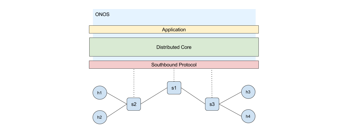
The following diagram demonstrates the high level overview of our environment. Rather than installing flows ourselves as we did in 3. Manual Flow Installation with Open vSwitch, we will issue application level commands to let the controller figure out how to provide connectivity.
5.1.1. Start and explore the SDN environment
We will begin by starting up our environment with several options. Before proceeding to install intents, make sure to initialize the environment with the following steps.
Step 1 Log-in to the environment and clean up any existing artifacts:
sdn@slab:~$ sudo pkill java
sdn@slab:~$ sudo mn -c
Step 2 Navigate to the mininet directory and start ONOS with the following configuration:
sdn@slab:~$ cd ~/onos/tools/dev/mininet
sdn@slab:~/onos/tools/dev/mininet$ sudo env ONOS_APPS=drivers,openflow,proxyarp,mobility\
          mn --custom onos.py --controller onos,1 --topo tree,2,2
*** Creating network
*** Adding controller
*** Creating network
*** Adding hosts:
(unpacking /tmp/onos1)onos1
...
mininet-onos>
env ONOS_APPS - This configuration allows us to specify applications to activate on our network controller. In this example, we are activating:
- drivers - default driver that speaks with the underlying devices
- openflow - enables providers to speak OpenFlow protocol with the devices
- proxyarp - service for processing ARP requests on behalf of applications
- mobility - handles flowmods when host moves from its original location
From a network administrator’s perspective, application level abstraction is helpful in simplifying the management process of complex environments.
Step 3 Take a look at the flows installed on one of the devices:
mininet-onos> sh ovs-ofctl dump-flows s1
NXST_FLOW reply (xid=0x4):
cookie=0x10000190260d7, duration=2885.872s, table=0, n_packets=1863, n_bytes=150903,
   idle_age=2, priority=40000,dl_type=0x88cc actions=CONTROLLER:65535
cookie=0x100006a526acd, duration=2885.865s, table=0, n_packets=1863, n_bytes=150903,
   idle_age=2, priority=40000,dl_type=0x8942 actions=CONTROLLER:65535
cookie=0x10000c42e0660, duration=2885.783s, table=0, n_packets=0, n_bytes=0,
   idle_age=2885, priority=40000,arp actions=CONTROLLER:65535
Thankfully, the controller has installed some initial flows for us. Let’s take a look at what they are.
1) The first flow definition forwards LLDP packets to the controller. The dl_type specifies ethertype Link Layer Discovery Protocol (0x88cc).
2) The second flow definition forwards BDDP packets to the controller. The dl_type specifies ethertype Broadcast Domain Discovery Protocol (0x8942). This is a lesser known protocol that is specific to SDN solutions.
3) The last flow definition forwards ARP requests to the controller. The dl_type is in plain text called arp.
Step 4 View the devices discovered by ONOS:
mininet-onos> onos devices
id=of:0000000000000001, available=true, role=MASTER, type=SWITCH  ...
id=of:0000000000000002, available=true, role=MASTER, type=SWITCH  ...
id=of:0000000000000003, available=true, role=MASTER, type=SWITCH  ...
Step 5 View the links discovered by ONOS:
mininet-onos> onos links
src=of:0000000000000001/1, dst=of:0000000000000002/3, type=DIRECT, state=ACTIVE, expected=false
src=of:0000000000000003/3, dst=of:0000000000000001/2, type=DIRECT, state=ACTIVE, expected=false
src=of:0000000000000001/2, dst=of:0000000000000003/3, type=DIRECT, state=ACTIVE, expected=false
src=of:0000000000000002/3, dst=of:0000000000000001/1, type=DIRECT, state=ACTIVE, expected=false
Notes
LLDP and BDDP are protocols used by the controller to discover links amongst devices. You can observe from the links command that all links are discovered and active.
Reference
For an excellent article on SDN Link discovery, visit: Current Trends of Topology Discovery in OpenFlow-based Software Defined Networks
Checkpoint
Proceed to the next section once you have a full understanding of the environment.
5.1.2. Install host-to-host intent
Let’s proceed to install the host-to-host intent using the ONOS CLI. If you have lost connection to the environment or shut-down Mininet, you can follow the steps from the previous section again to launch the environment.
Step 1 Ping from h1 to h4 to test for connectivity:
mininet-onos> h1 ping -c 4 h4
PING 10.0.0.4 (10.0.0.4) 56(84) bytes of data.

--- 10.0.0.4 ping statistics ---
4 packets transmitted, 0 received, 100% packet loss, time 2999ms
The ping is unsuccessful because no rules have been established for the packets yet. However, since we used the ping command and sent an ARP request (transmitted to the controller), ONOS now has knowledge of the existence of h1 and h4.
Step 2 Verify that ONOS has discovered h1 and h4:
mininet-onos> onos hosts
id=46:F3:30:54:1E:D9/None, mac=46:F3:30:54:1E:D9, location=of:0000000000000003/2,
   vlan=None, ip(s)=[10.0.0.4], configured=false
id=5A:F4:E0:4A:65:65/None, mac=5A:F4:E0:4A:65:65, location=of:0000000000000002/1,
   vlan=None, ip(s)=[10.0.0.1], configured=false
Notice the ip(s) field for the corresponding host number - and that other hosts (h2 and h3) are not yet discovered by ONOS.
Note down the host id field from the output above. A host id is comprised of its MAC address and Vlan ID. In the above example, h1-ID = 5A:F4:E0:4A:65:65/None. You will need this ID in the next step.
Step 3 Drop into the ONOS CLI and invoke the add-host-intent command.
mininet-onos> onos
...
onos> add-host-intent <h1-ID> <h4-ID>
Host to Host intent submitted:
HostToHostIntent{id=0x0, key=0x0, appId=DefaultApplicationId{id=2, name=org.onosproject.cli},
   priority=100, resources=[5A:F4:E0:4A:65:65/None, 46:F3:30:54:1E:D9/None],
   selector=DefaultTrafficSelector{criteria=[]}, treatment=DefaultTrafficTreatment{immediate=[NOACTION],
   deferred=[], transition=None, meter=None, cleared=false, metadata=null},
   constraints=[LinkTypeConstraint{inclusive=false, types=[OPTICAL]}], one=5A:F4:E0:4A:65:65/None,
   two=46:F3:30:54:1E:D9/None}
Notes
You can use <tab> completion to fill out the arguments once you are in the onos> prompt.
The command has returned successfully with an object describing the intent.
Step 4 Log-out of the onos> prompt:
onos> logout
mininet-onos>
Step 5 Try to ping from h1 to h4 again:
mininet-onos> h1 ping -c 4 h4
PING 10.0.0.4 (10.0.0.4) 56(84) bytes of data.
64 bytes from 10.0.0.4: icmp_seq=1 ttl=64 time=0.309 ms
64 bytes from 10.0.0.4: icmp_seq=2 ttl=64 time=0.053 ms
64 bytes from 10.0.0.4: icmp_seq=3 ttl=64 time=0.052 ms
64 bytes from 10.0.0.4: icmp_seq=4 ttl=64 time=0.054 ms

--- 10.0.0.4 ping statistics ---
4 packets transmitted, 4 received, 0% packet loss, time 2997ms
rtt min/avg/max/mdev = 0.052/0.117/0.309/0.110 ms
mininet-onos>
After a simple host-to-host intent installation, the ICMP packets are now properly forwarded. Notice that you did not have to specify any ARP forwarding rules. This is handled by ONOS as part of the proxyarp service installed in 5.1.1. Start and explore the SDN environment.
Step 6 Identify the flows installed by ONOS on s1:
mininet-onos> sh ovs-ofctl dump-flows s1
NXST_FLOW reply (xid=0x4):
cookie=0x50000031832820, duration=848.418s, table=0, n_packets=4, n_bytes=392, idle_age=606,
    priority=100,in_port=1,dl_src=5a:f4:e0:4a:65:65,dl_dst=46:f3:30:54:1e:d9 actions=output:3
cookie=0x500000823b3a60, duration=848.418s, table=0, n_packets=4, n_bytes=392, idle_age=606,
    priority=100,in_port=3,dl_src=46:f3:30:54:1e:d9,dl_dst=5a:f4:e0:4a:65:65 actions=output:1
There are two flows in addition to the ones we have explored beforehand. See if you can make sense of each field of the flows.
Step 7 Clean up the environment in preparation for the next exercise:
mininet-onos> exit
...
sdn@slab:~$ sudo pkill java
sdn@slab:~$ sudo mn -c
Great job! You have successfully connected two endpoints using a software defined network controller!
Checkpoint
How does this process compare to manually installing flows?
5.2. Installing Applications for Connectivity
One of the advantages of having a software defined network is the ease of administration. In ONOS, this is further realized by its easy-to-use graphical user interface (gui).
In this segment, we will use the graphical user interface to install an application called Reactive Forwarding. As a result of installing this application, a packet sender will receive desired connection on-demand without previously having been configured for connectivity.
We will use the same topology as described in the beginning of this chapter.
Step 1 Log-in to your environment and launch Mininet along with ONOS:
sdn@slab:~$ sudo env ONOS_APPS=drivers,openflow,proxyarp,mobility mn --custom onos.py \
            --controller onos,1 --topo tree,2,2
*** Creating network
*** Adding controller
*** Creating network
*** Adding hosts:
(unpacking /tmp/onos1)onos1
...
mininet-onos>
As mentioned previously, several applications are launched by this command along with ONOS. We have omitted starting reactive forwarding application for demonstration purposes.
Step 2 Begin by issuing a continuous ping across h2 to h3:
mininet-onos> h2 ping h3
PING 10.0.0.3 (10.0.0.3) 56(84) bytes of data.
There will be no response, but don’t worry! Keep the ping running and open a browser tab (Chrome recommended).
Step 3 Open a browser and navigate to the ONOS user interface http://<slab-IP>:8181/onos/ui/:
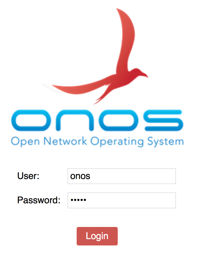
Log-in using the credentials onos/rocks.
Step 4 Press h on your keyboard to show hosts:
As expected, ONOS has discovered hosts h2 and h3 from the incoming ARP request.
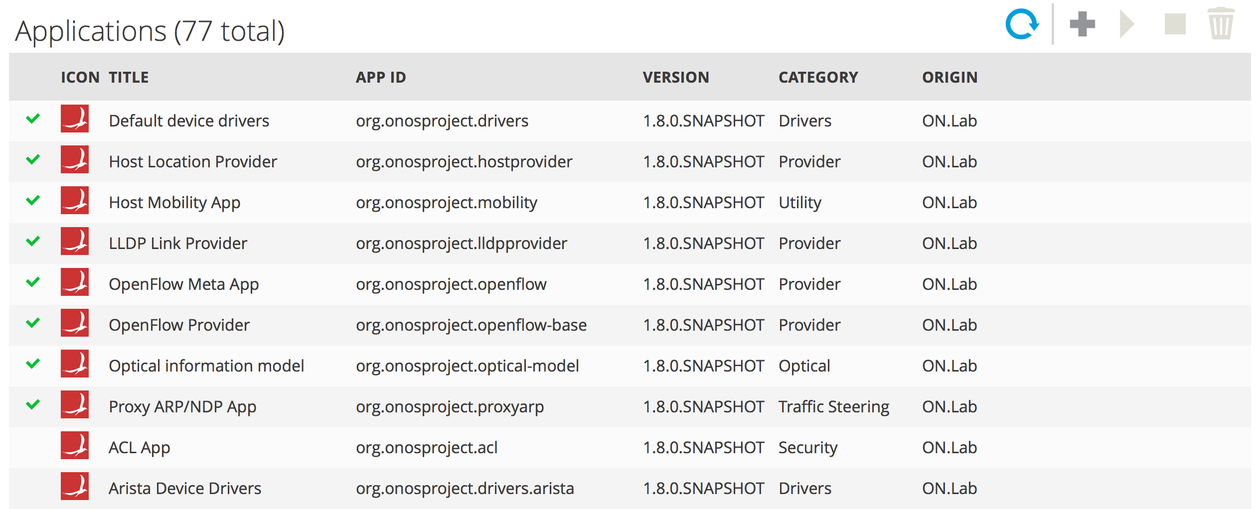
Step 5 On the top left corner, click on the menu icon and select Applications:
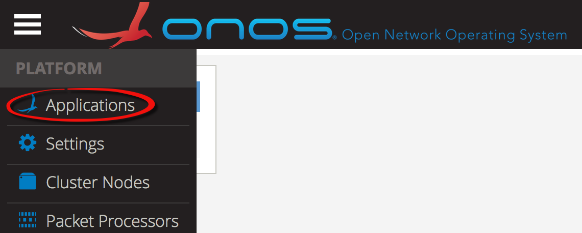
You will see a table of installed and available applications. From here, you can either select an Application file to upload or simply activate an existing application.
Step 6 Scroll down in the list of applications and click on Reactive Forwarding App:
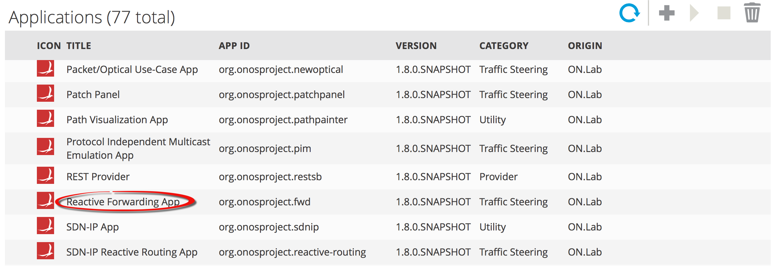
Step 7 On the top right of the table, click the Play icon to activate the application:
Click OK in the Confirm Action dialogue.
Step 8 Return to the command line where the ping is being issued. You will notice that connectivity has been restored!:
PING 10.0.0.3 (10.0.0.3) 56(84) bytes of data.

64 bytes from 10.0.0.3: icmp_seq=1134 ttl=64 time=6.69 ms
64 bytes from 10.0.0.3: icmp_seq=1135 ttl=64 time=0.280 ms
64 bytes from 10.0.0.3: icmp_seq=1136 ttl=64 time=0.045 ms
64 bytes from 10.0.0.3: icmp_seq=1137 ttl=64 time=0.046 ms
64 bytes from 10.0.0.3: icmp_seq=1138 ttl=64 time=0.046 ms
Keep the ping running and return to the user interface.
Step 9 Navigate back to the Topology page by clicking on the menu on the navigation bar.
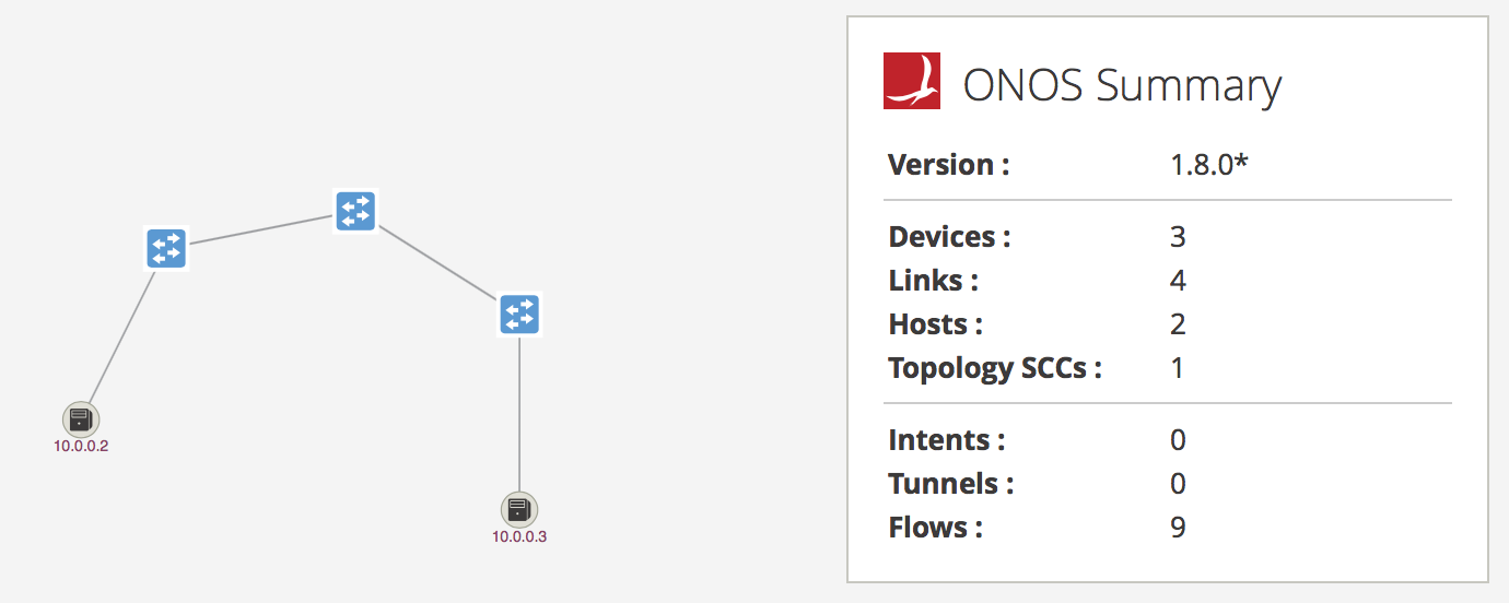
Step 10 Press a on your keyboard to monitor traffic using flow stats:
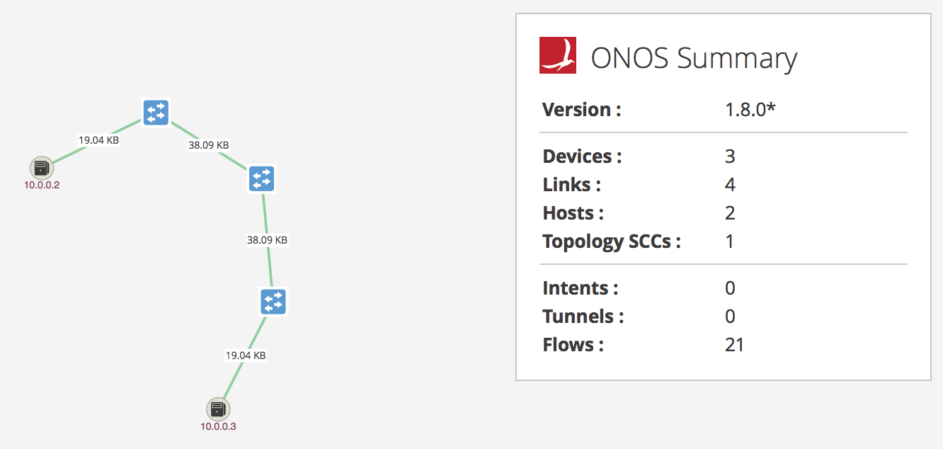
Notice the increased number of Flows in the summary tab. ONOS has installed additional flows reactively to allow connectivity.
Notes
Feel free to explore additional aspects of the ONOS graphical user interface!
Step 11 Return to the CLI and clean up the environment:
mininet-onos> exit
...
sdn@slab:~$ sudo pkill java
sdn@slab:~$ sudo mn -c
Checkpoint
Use the ONOS gui to install Reactive Forwarding application and enable connectivity
5.3. Traffic Re-routing
In the following exercise, we will explore how the SDN controller can solve network entity failures. Unlike traditional IP networks where each node can act autonomously and make forwarding decisions, a failure in a software defined network must alert the controller.
This means that a truly proactive network recovery will incur additional latency as packets that miss the table is sent to the controller in hopes that the controller knows what to do with it. From there, the controller must first be knowledgeable about the state of the network and then decide a new path must be calculated for the packet. Finally, a new flow rule will be sent back to the switches, if possible, in order to fulfill the packet’s request.
Although not part of this exercise, it is possible to predefine a backup path on the switch in case of a network failure. This method is quicker than contacting the controller. However, it does not offer an opportunity for the controller to calculate the most optimal path, and does not necessarily guarantee that the backup path is active.
5.3.1. Create a triangle topology
To test the reroute functionality we will create a topology with 3 switches connected together in a loop. Rather than using a predefined Mininet topology, we will create our own using Python methods.
Step 1 Navigate to the directory containing onos.py:
sdn@slab:~$ cd ~/onos/tools/dev/mininet/
Step 2 Create and open the file for editing and insert the following Python topology code:
sdn@slab:~/onos/tools/dev/mininet$ vim triangle.py
...

# triangle.py file contents
from mininet.topo import Topo

class MyTopo( Topo ):

   def __init__( self ):

      Topo.__init__( self )

      leftHost = self.addHost( 'h1' )
      rightHost = self.addHost( 'h2' )
      leftSwitch = self.addSwitch( 's1' )
      topSwitch = self.addSwitch( 's2' )
      rightSwitch = self.addSwitch( 's3' )

      self.addLink( leftHost, leftSwitch )
      self.addLink( leftSwitch, topSwitch )
      self.addLink( leftSwitch, rightSwitch )
      self.addLink( topSwitch, rightSwitch )
      self.addLink( rightSwitch, rightHost )

topos = { 'mytopo': ( lambda: MyTopo() ) }
Save the file and exit.
Step 3 Run the following command to start ONOS with the new triangle topology:
sdn@slab:~/onos/tools/dev/mininet$ sudo env ONOS_APPS=drivers,openflow,proxyarp,mobility \
         mn --custom onos.py,triangle.py --topo mytopo --controller onos,1
*** Creating network
*** Adding controller
*** Creating network
...
mininet-onos>
Notes
If you are getting errors when starting ONOS, your triangle.py topology file may not be correct. Furthermore, ensure that the spacing of parameters in the command is as provided.
Step 4 Send one ping across h1 and h2 so that ONOS discovers the hosts:
mininet-onos> h1 ping -c 1 h2
PING 10.0.0.2 (10.0.0.2) 56(84) bytes of data.

--- 10.0.0.2 ping statistics ---
1 packets transmitted, 0 received, 100% packet loss, time 0ms
mininet-onos>
Step 5 Navigate to the ONOS user interface on your browser and log-in using the following credentials (Chrome recommended):
| URL | http://<slab-IP>:8181/onos/ui/ |
| User | onos |
| Password | rocks |
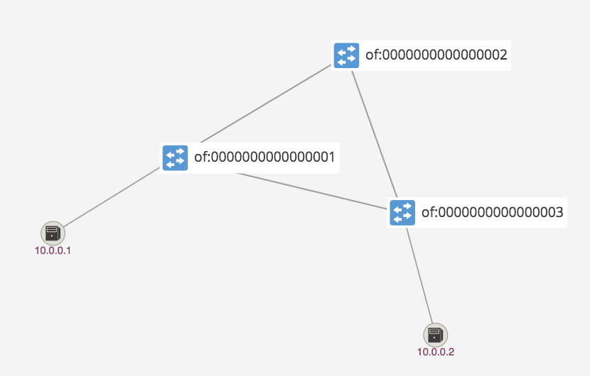
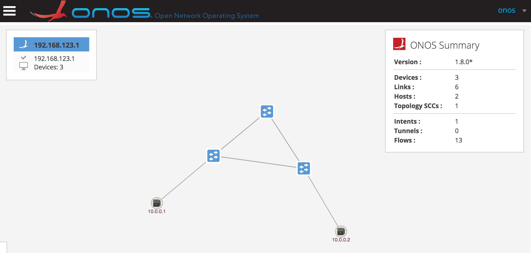
Step 6 Use shortcuts h on the keyboard to display hosts and l (lower case L) to display device labels. You should see the following topology:
Checkpoint
After verifying the topology, proceed to the next section without terminating the environment.
5.3.2. Add intents using the GUI
With the topology created in 5.3.1. Create a triangle topology, we will provide connectivity between the hosts using the GUI functionality.
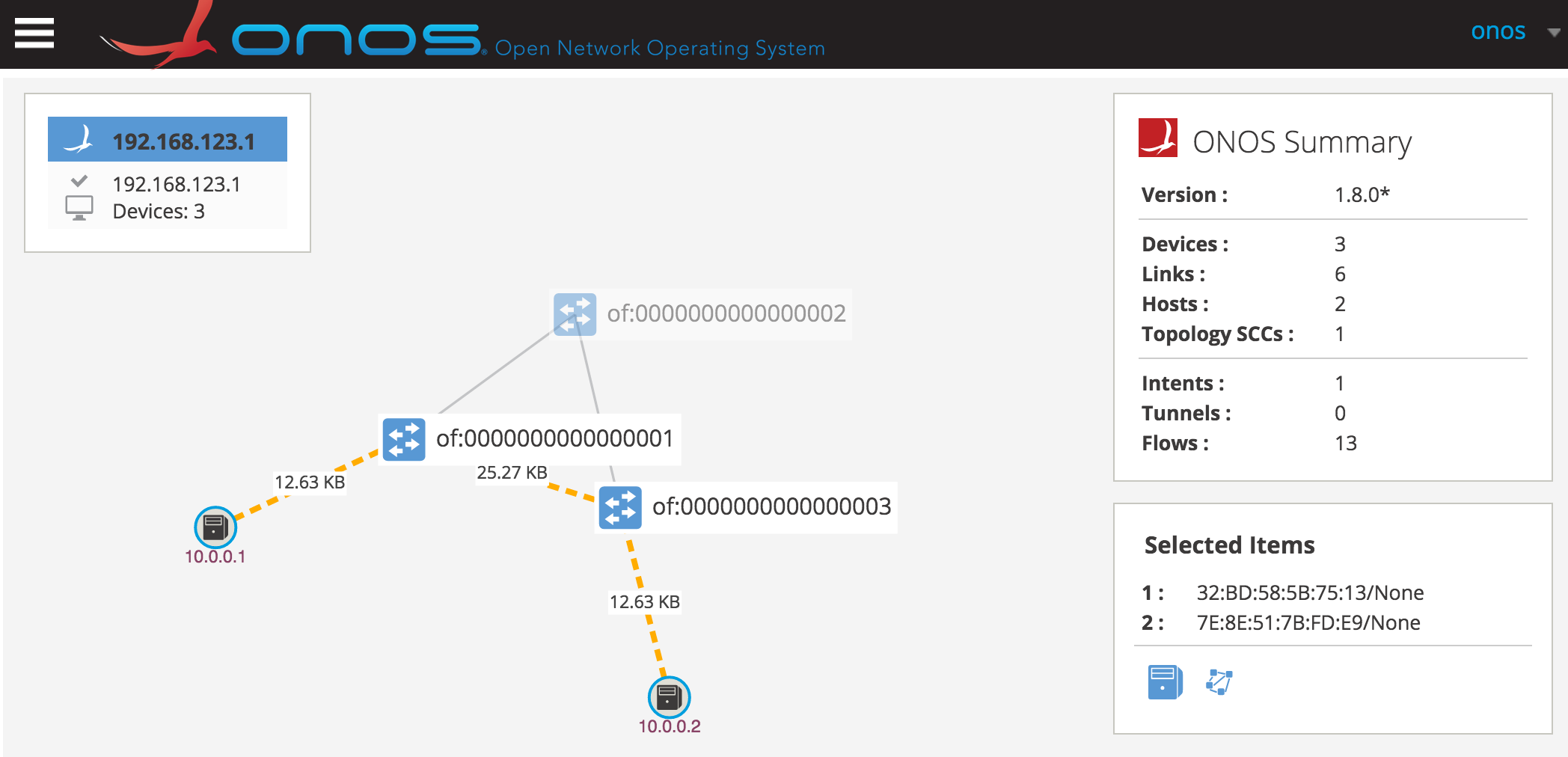
Step 1 Log-in to the ONOS user interface on your browser and view the Topology page:
Step 2 Hold down Shift and click on h1 icon (10.0.0.1) and h2 (10.0.0.2) icon to select both hosts:
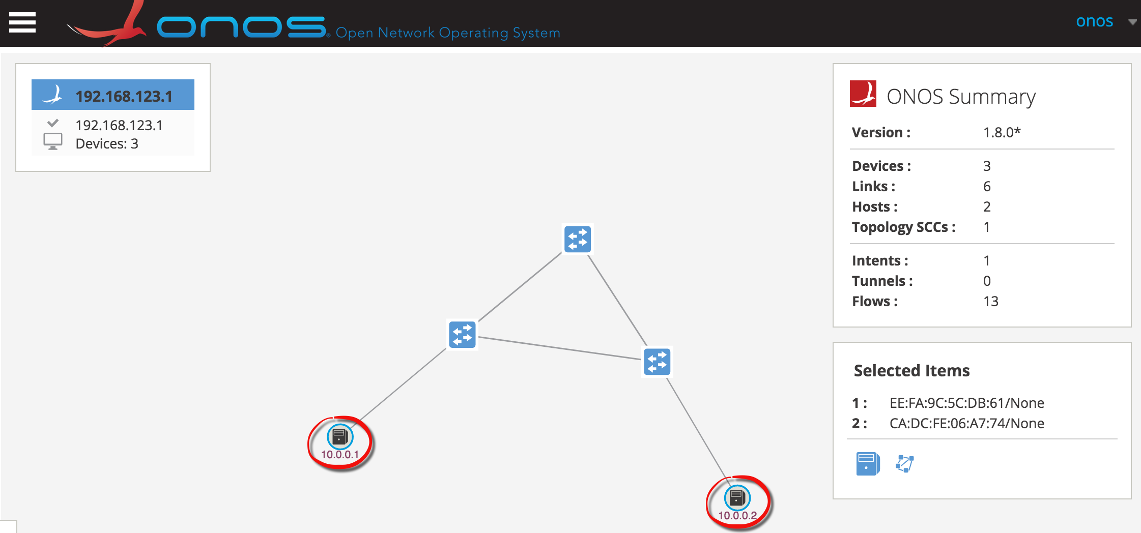
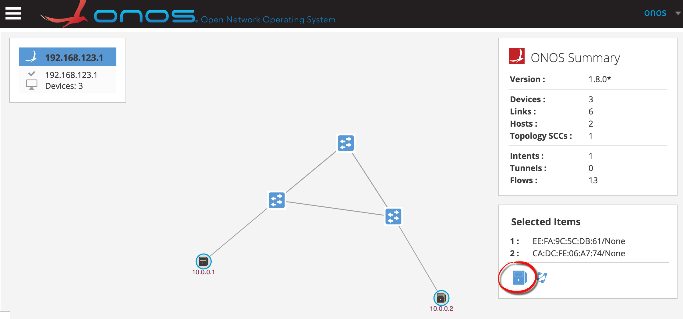
Step 3 Click on the server icon under Selected Items dialog:
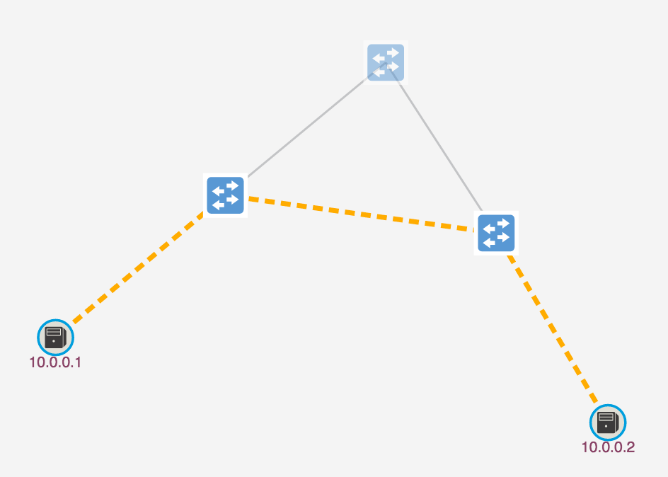
Step 4 Observe the path highlighted which indicates the path of the forwarding rules installed by ONOS to provide host connectivity:
Step 5 Switch back to your terminal with the mininet-onos> prompt and ping from h1 to h2:
mininet-onos> h1 ping -c 3 h2
PING 10.0.0.2 (10.0.0.2) 56(84) bytes of data.
64 bytes from 10.0.0.2: icmp_seq=1 ttl=64 time=0.196 ms
64 bytes from 10.0.0.2: icmp_seq=2 ttl=64 time=0.035 ms
64 bytes from 10.0.0.2: icmp_seq=3 ttl=64 time=0.048 ms
...
mininet-onos>
You have successfully established connectivity between the hosts.
Checkpoint
Continue on to the next section with the session active. If you lost connection to your environment, revert to step 3 of 5.3.1. Create a triangle topology and make sure to follow through the rest of the steps before proceeding.
5.3.3. Simulate port failure
As you have observed from the previous section, simply defining two hosts to be connected resulted in the network controller choosing the shortest path. In a more complex scenario, the controller may take into account the weight of a link determined by factors such as latency and throughput or user induced artificial weight.
In this exercise, we will see how the controller behaves when a connection failure is detected on an established path.
Step 1 In your mininet-onos> prompt, start a ping between h1 and h2. We will keep this running for the duration of this section:
mininet-onos> h1 ping h2
PING 10.0.0.2 (10.0.0.2) 56(84) bytes of data.
64 bytes from 10.0.0.2: icmp_seq=1 ttl=64 time=0.202 ms
64 bytes from 10.0.0.2: icmp_seq=2 ttl=64 time=0.041 ms
64 bytes from 10.0.0.2: icmp_seq=3 ttl=64 time=0.050 ms
64 bytes from 10.0.0.2: icmp_seq=4 ttl=64 time=0.048 ms
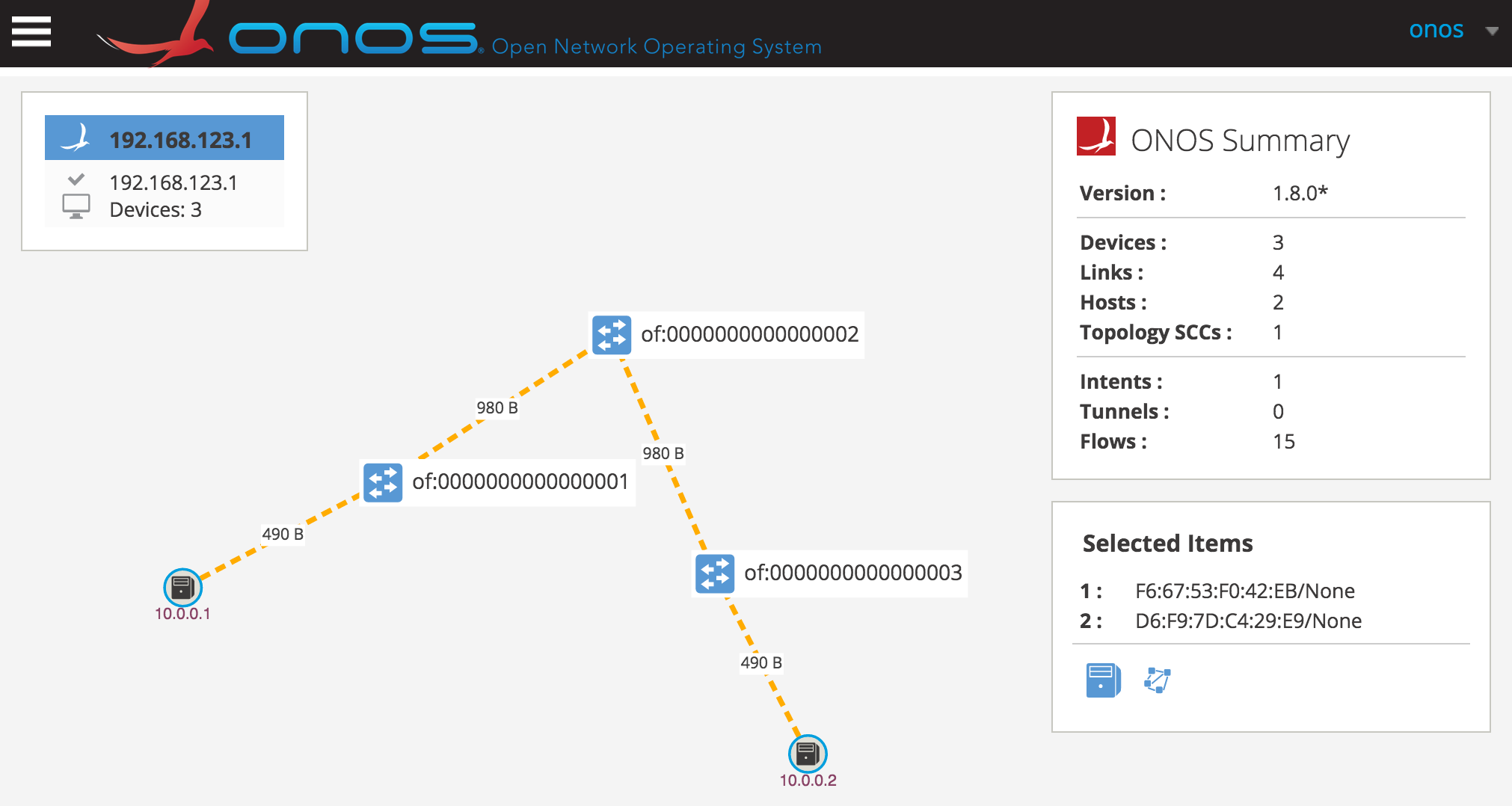
Step 2 Log-in to the ONOS ui and enable the following features using the shortcuts listed:
- traffic monitoring - tr(a)ffic
- device labels - (l)abels
- hosts - (h)osts
You should see the following graphical elements on the topology.
Notes
Sidenote for the curious: Each switch is instructed by the controller to send out link discovery (LLDP) messages with a probe payload. By default, each device will send out discovery packets from all its ports every 3 seconds.
This explains the increased traffic between s1 and s3 compared to s1 and h1. s1 sends out a discovery message to h1 and s3. s1 also receives a discovery message from device s3. The hosts do not send out any type of discovery messages.
Step 3 Let the ping continue to run and open a new terminal window. Connect to the lab environment:
$ ssh sdn@<slab-IP>
# password: rocks
...
sdn@slab:~$
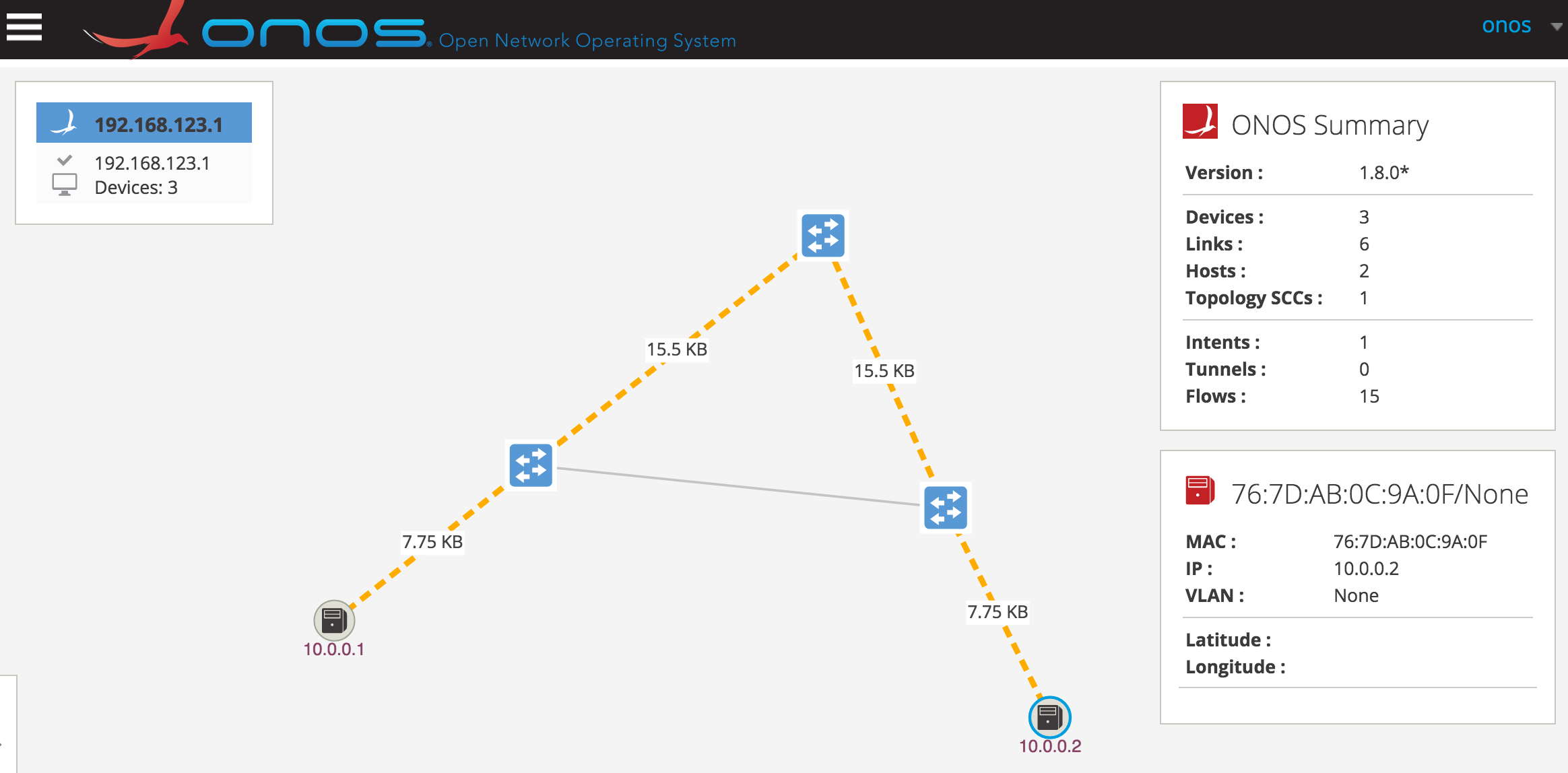
Step 4 Use the ovs-vsctl tool to delete the port between s1 and s3:
sdn@slab:~$ sudo ovs-vsctl del-port s1-eth3
sdn@slab:~$
Take a look at the ONOS user interface. You will notice that ping sequence is uninterrupted and shows a new path in which the traffic is flowing.
Step 5 Let’s add the port back to the topology. What do you suppose will happen? You can close this terminal after executing the command.
sdn@slab:~$ sudo ovs-vsctl add-port s1 s1-eth3
sdn@slab:~$ logout
As far as the controller is concerned, the link is up but traffic is not directed back to the link to which original intents were installed. In fact, the old intents were purged with the loss of connection and new ones were installed. The controller will not attempt to find an optimal path upon new link discoveries. This default behavior safeguards against “flickering” events - cases where devices may appear to be switching states constantly which can cause severe network congestion and resource exhaustion.
Step 6 Press ctrl+C to kill the ping on mininet-onos> prompt and continue on to the next section:
mininet-onos>
...
64 bytes from 10.0.0.2: icmp_seq=1 ttl=64 time=0.202 ms
64 bytes from 10.0.0.2: icmp_seq=2 ttl=64 time=0.041 ms
64 bytes from 10.0.0.2: icmp_seq=3 ttl=64 time=0.050 ms
64 bytes from 10.0.0.2: icmp_seq=4 ttl=64 time=0.048 ms
^C
mininet-onos>
5.3.4. Simulate switch failure
Now that we have the connection restored between s1 and s3, let’s see if loss of s2 will re-route traffic back to the shortest path. Furthermore, we will monitor controller’s OpenFlow traffic to view the underlying messages that prompt the controller to recompute the required flows.
Notes
In this section, we will be opening multiple terminal windows for various processes. Take care to follow instructions closely to execute commands in the correct window.
Before we begin happily disconnecting switches, lets first gather some information about the environment to fully understand the packet dissection later on. We will gather the important details in a table.
Step 1 In the mininet-onos> prompt from previous window, run the net command to see the connection:
mininet-onos> net
h1 h1-eth0:s1-eth1
h2 h2-eth0:s3-eth3
s1 lo:  s1-eth1:h1-eth0 s1-eth2:s2-eth1 s1-eth3:s3-eth1
s2 lo:  s2-eth1:s1-eth2 s2-eth2:s3-eth2
s3 lo:  s3-eth1:s1-eth3 s3-eth2:s2-eth2 s3-eth3:h2-eth0
c0
onos1 onos1-eth0:cs1-eth1
nat0 nat0-eth0:cs1-eth2
cs1 lo:  cs1-eth1:onos1-eth0 cs1-eth2:nat0-eth0
This tells us that the ONOS is connected to cs1-eth1. This is the interface we will listen to for OpenFlow traffic.
Step 2 In the mininet-onos> prompt, list the ports from the ONOS command:
mininet-onos> onos ports
id=of:0000000000000001, available=true, role=MASTER, type=SWITCH, mfr=Nicira, Inc.,
hw=Open vSwitch, sw=2.0.2, serial=None, driver=ovs, channelId=192.168.123.2:43437,
managementAddress=192.168.123.2, protocol=OF_10
  port=LOCAL, state=enabled, type=copper, speed=0 , portName=s1, portMac=36:b9:2f:8d:80:47
  port=1, state=enabled, type=copper, speed=10000 , portName=s1-eth1, portMac=1a:e5:94:c1:24:73
  port=2, state=enabled, type=copper, speed=10000 , portName=s1-eth2, portMac=7e:2f:5d:6b:2c:26
  port=3, state=enabled, type=copper, speed=10000 , portName=s1-eth3, portMac=ea:3d:6a:2a:e7:bf
id=of:0000000000000002, available=true, role=MASTER, type=SWITCH, mfr=Nicira, Inc.,
hw=Open vSwitch, sw=2.0.2, serial=None, driver=ovs, channelId=192.168.123.2:43436,
managementAddress=192.168.123.2, protocol=OF_10
  port=LOCAL, state=enabled, type=copper, speed=0 , portName=s2, portMac=aa:9e:68:ca:f6:46
  port=1, state=enabled, type=copper, speed=10000 , portName=s2-eth1, portMac=e6:1a:2e:9d:ab:27
  port=2, state=enabled, type=copper, speed=10000 , portName=s2-eth2, portMac=1e:20:52:42:56:95
id=of:0000000000000003, available=true, role=MASTER, type=SWITCH, mfr=Nicira, Inc.,
hw=Open vSwitch, sw=2.0.2, serial=None, driver=ovs, channelId=192.168.123.2:43438,
managementAddress=192.168.123.2, protocol=OF_10
  port=LOCAL, state=enabled, type=copper, speed=0 , portName=s3, portMac=46:f9:55:16:bd:4f
  port=1, state=enabled, type=copper, speed=10000 , portName=s3-eth1, portMac=72:2d:a7:5a:0d:1a
  port=2, state=enabled, type=copper, speed=10000 , portName=s3-eth2, portMac=2a:47:6a:92:da:1c
  port=3, state=enabled, type=copper, speed=10000 , portName=s3-eth3, portMac=5a:c9:77:88:df:a3
The onos ports command shows detailed information about each switch. The important thing to note here is that the managementAddress of all switches is the same (192.168.123.2). This means that any communication between ONOS and the switch will take place at 192.168.123.1 (ONOS) <-> 192.168.123.2 (Switch). Individual switches are distinguished by the port number in the channelId field.
Notes
This setup is unique to our all-in-one environment. It allows us to emulate separate networks for ONOS and its devices. In a real world scenario, each switch may have its own management address, as well as have a ‘SLAVE’ role to ONOS when there are multiple ONOS instances.
Here is a summary of the artifacts we have gathered.
Artifact table
| Controller traffic interface | cs1-eth1 |
| Switch mgmt address | 192.168.123.2 |
| Controller address | 192.168.123.1 |
| S2 Channel ID - Port number | 43436 |
Step 3 Resume the ping from h1 to h2 and leave the ping running:
mininet-onos> h1 ping h2
...
Step 4 Open a new terminal and log-in to the lab environment:
$ ssh sdn@<slab-IP>
# password: rocks
...
sdn@slab:~$
Step 5 Run tshark, a wireshark command line utility used to observe and dissect network traffic including OpenFlow Protocol:
sdn@slab:~$ tshark -i cs1-eth1 > output.txt
Capturing on 'cs1-eth1'
...
Step 6 Open a new terminal window and log-in to the lab environment. This time we will use it for invoking ovs-vsctl commands without interrupting other processes:
$ ssh sdn@<slab-IP>
# password: rocks
...
sdn@slab:~$
Step 7 Remove s1 from the controller assignment to simulate a switch-down behavior. You can close the window after running this command:
sdn@slab:~$ sudo ovs-vsctl del-controller s2
sdn@slab:~$ logout
In the user interface, you can see that the traffic has been rerouted to flow between s1 and s3.

Step 7 Go back to the tshark process and kill it by pressing ctrl+C on the Keyboard:
Capturing on 'cs1-eth1'
6892 ^C
sdn@slab:~$
The output of the process is saved in ~/output.txt
Step 8 First, lets analyze the switch disconnection sequence:
sdn@slab:~$ cat output.txt | grep -i -A 1 'FIN'
313  11.286645 192.168.123.2 -> 192.168.123.1 TCP 66 43436 > openflow [FIN, ACK] Seq=52837 Ack=1945
   Win=72 Len=0 TSval=584524397 TSecr=584523929
314  11.287204 192.168.123.1 -> 192.168.123.2 TCP 66 openflow > 43436 [FIN, ACK] Seq=1945 Ack=52838
   Win=363 Len=0 TSval=584524397 TSecr=584524397
315  11.287429 192.168.123.2 -> 192.168.123.1 TCP 66 43436 > openflow [ACK] Seq=52838 Ack=1946
   Win=72 Len=0 TSval=584524397 TSecr=584524397
The FIN messages indicate that the switch (192.168.123.2) terminated connection with the controller (192.168.123.1). From its port number 43436 we can conclude that this is S2.
Notes
The method we used to shutdown the switch is more graceful than what may be experienced in production. For example, if a switch power is unplugged it will have no chance to send a ‘FIN’ message. Instead, LLDP - Link layer discovery protocol by its neighbors will have to detect its absence leading to longer downtime.
Step 9 Next, take a look at the OpenFlow message exchange between the controller and dataplane. Notice the packet number (first column) continues from Step 8:
sdn@slab:~$ cat output.txt | grep -i -A 30 'of_flow_delete'
331  11.329196 192.168.123.1 -> 192.168.123.2 OF 1.0 138 of_flow_delete
332  11.329234 192.168.123.1 -> 192.168.123.2 OF 1.0 138 of_flow_delete
333  11.329246 192.168.123.1 -> 192.168.123.2 OF 1.0 74 of_barrier_request
334  11.329359 192.168.123.2 -> 192.168.123.1 OF 1.0 154 of_flow_removed
335  11.329419 192.168.123.2 -> 192.168.123.1 OF 1.0 154 of_flow_removed
336  11.329432 192.168.123.2 -> 192.168.123.1 OF 1.0 74 of_barrier_reply
338  11.337193 192.168.123.1 -> 192.168.123.2 OF 1.0 138 of_flow_delete
339  11.337278 192.168.123.2 -> 192.168.123.1 OF 1.0 154 of_flow_removed
341  11.337438 192.168.123.1 -> 192.168.123.2 OF 1.0 138 of_flow_delete
342  11.337499 192.168.123.2 -> 192.168.123.1 OF 1.0 154 of_flow_removed
343  11.337633 192.168.123.1 -> 192.168.123.2 OF 1.0 74 of_barrier_request
344  11.337675 192.168.123.2 -> 192.168.123.1 OF 1.0 74 of_barrier_reply
345  11.352640 192.168.123.1 -> 192.168.123.2 OF 1.0 146 of_flow_add
346  11.352871 192.168.123.1 -> 192.168.123.2 OF 1.0 146 of_flow_add
347  11.352897 192.168.123.1 -> 192.168.123.2 OF 1.0 74 of_barrier_request
349  11.352961 192.168.123.2 -> 192.168.123.1 OF 1.0 74 of_barrier_reply
350  11.359194 192.168.123.1 -> 192.168.123.2 OF 1.0 146 of_flow_add
351  11.359392 192.168.123.1 -> 192.168.123.2 OF 1.0 146 of_flow_add
...
Notes
Some packets have been omitted in the example output above to highlight the relevant OpenFlow communication.
Here is a summary of the packets we captured.
- of_flow_delete: A FlowMod message sent by the controller to switch with instructions to delete particular flow.
- of_flow_removed: A FlowMod message sent by the switch to controller indicating that a flow has been removed from its table.
- of_flow_add: A FlowMod message sent by the controller to switch with a command that specifies the type of flow table modification.
- of_barrier_request: A confirmation message sent by the controller to switch that ensures previous commands have been fulfilled by the switch. The switch MUST complete processing all previous messages before proceeding to any other commands it received.
- of_barrier_reply: A confirmation message sent by the switch to the controller indicating it has finished all tasks prior to receiving of_barrier_request.
In this exchange of packets, we can observe that the network controller is in charge of handling switch events from its disconnection point all the way to deleting, computing, and installing new flows to restore connectivity to hosts.
Reference
For more information on OpenFlow messages, visit OpenFlow Switch Specification
Checkpoint
Congratulations! You have finished the SDN50 lab.
![]()
Table Of Contents
- 1. Explore the Lab Environment
- 2. Mininet
- 3. Manual Flow Installation with Open vSwitch
- 4. Open Network Operating System (ONOS)
- 5. Software Defined Networking