6. OpenStack Networking
In this chapter, we will explore an OpenStack environment configured to use Neutron with VXLAN tunneling segmentation.
| Chapter Details | |
|---|---|
| Chapter Goal | OpenStack networking practice |
| Chapter Sections | |
6.1. Prerequisites
Check that the following prerequisite has been met:
- You have access to the lab environment
6.2. Underlying Networks
Step 1 Start Virtual Machine Manager:
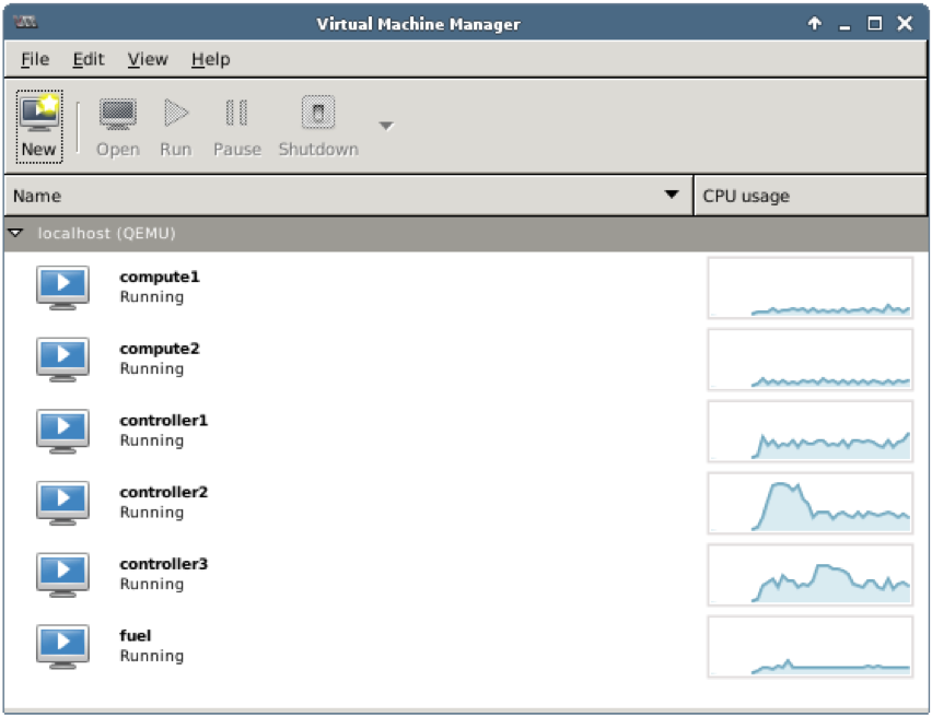
Check that the following VMs are up and running:
- 2 compute nodes: compute1, compute2
- 3 controller nodes: controller1, controller2, controller3
- 1 Fuel node: fuel
Step 2 From the main menu choose Edit, then Connection Details to open Connection Details window. Choose Virtual Networks tab:
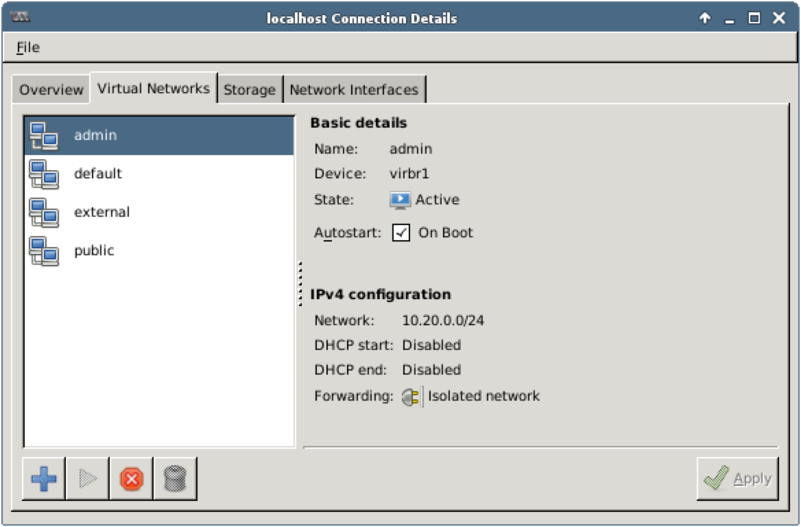
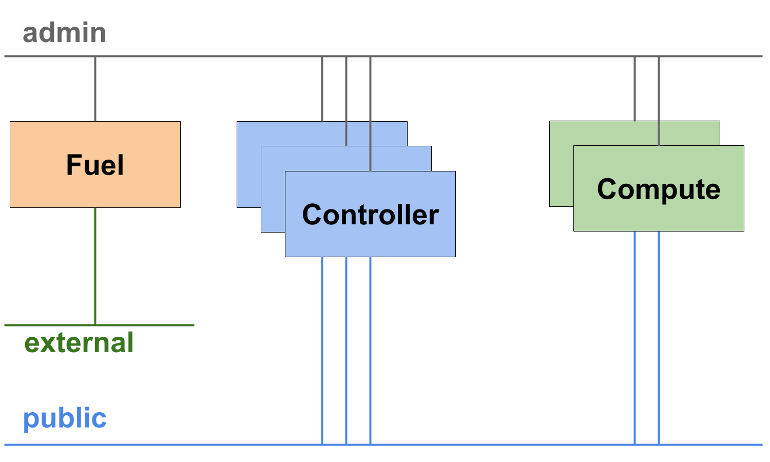
In this environment, the following networks are used:
- admin 10.20.0.0/24, isolated
- public 172.16.0.0/24, NAT
- external 172.16.1.0/24, NAT
The configuration of the existing OpenStack environment is similar to the configuration of the highly available environment you have deployed in the chapter 5. HA Deployment. There are only two differences:
- In the existing environment we have two compute nodes. We will use them in this chapter to explore how connectivity works for VMs started on different compute nodes.
- The existing environment is configured to use Neutron with VXLAN tunneling segmentation.
6.3. OpenStack Networks
Let’s explore OpenStack networks.
Step 1 Open Terminal Emulator, log in to any controller node and execute the following commands to see OpenStack networks:
root@node-4:~# source openrc
root@node-4:~# neutron net-list
+--------------------------------------+-----------+-------------------------------------------------------+
| id                                   | name      | subnets                                               |
+--------------------------------------+-----------+-------------------------------------------------------+
| c4e2f2ba-53a3-472b-9b8e-5f2b5b1e05e2 | net04     | b1372191-3153-44df-a70e-9a41c8e2bfcb 192.168.111.0/24 |
| 7fcb4c69-eb42-415a-8904-ca73817fa526 | net04_ext | 0dafb35f-1411-4b1c-a69d-5d64f809cab7 172.16.0.0/24    |
+--------------------------------------+-----------+-------------------------------------------------------+
Step 2 Use the following commands to explore the existing networks:
root@node-4:~# neutron net-show net04
+---------------------------+--------------------------------------+
| Field                     | Value                                |
+---------------------------+--------------------------------------+
| admin_state_up            | True                                 |
| id                        | c4e2f2ba-53a3-472b-9b8e-5f2b5b1e05e2 |
| mtu                       | 1450                                 |
| name                      | net04                                |
| provider:network_type     | vxlan                                |
| provider:physical_network |                                      |
| provider:segmentation_id  | 2                                    |
| router:external           | False                                |
| shared                    | False                                |
| status                    | ACTIVE                               |
| subnets                   | b1372191-3153-44df-a70e-9a41c8e2bfcb |
| tenant_id                 | 77ae2edfa20f4bc48b62d08c1ae2614b     |
+---------------------------+--------------------------------------+

root@node-4:~# neutron net-show net04_ext
+---------------------------+--------------------------------------+
| Field                     | Value                                |
+---------------------------+--------------------------------------+
| admin_state_up            | True                                 |
| id                        | 7fcb4c69-eb42-415a-8904-ca73817fa526 |
| mtu                       | 0                                    |
| name                      | net04_ext                            |
| provider:network_type     | local                                |
| provider:physical_network |                                      |
| provider:segmentation_id  |                                      |
| router:external           | True                                 |
| shared                    | False                                |
| status                    | ACTIVE                               |
| subnets                   | 0dafb35f-1411-4b1c-a69d-5d64f809cab7 |
| tenant_id                 | 77ae2edfa20f4bc48b62d08c1ae2614b     |
+---------------------------+--------------------------------------+
Step 3 Use the following command to view the subnets:
root@node-4:~# neutron subnet-list
+--------------------------------------+-------------------+------------------+------------------------------------------------------+
| id                                   | name              | cidr             | allocation_pools                                     |
+--------------------------------------+-------------------+------------------+------------------------------------------------------+
| b1372191-3153-44df-a70e-9a41c8e2bfcb | net04__subnet     | 192.168.111.0/24 | {"start": "192.168.111.2", "end": "192.168.111.254"} |
| 0dafb35f-1411-4b1c-a69d-5d64f809cab7 | net04_ext__subnet | 172.16.0.0/24    | {"start": "172.16.0.130", "end": "172.16.0.254"}     |
+--------------------------------------+-------------------+------------------+------------------------------------------------------+
Step 4 Use the subnet names from the output above to explore the existing subnets in net04 and net04_ext networks:
root@node-4:~# neutron subnet-show net04__subnet
+-------------------+------------------------------------------------------+
| Field             | Value                                                |
+-------------------+------------------------------------------------------+
| allocation_pools  | {"start": "192.168.111.2", "end": "192.168.111.254"} |
| cidr              | 192.168.111.0/24                                     |
| dns_nameservers   | 8.8.4.4                                              |
|                   | 8.8.8.8                                              |
| enable_dhcp       | True                                                 |
| gateway_ip        | 192.168.111.1                                        |
| host_routes       |                                                      |
| id                | b1372191-3153-44df-a70e-9a41c8e2bfcb                 |
| ip_version        | 4                                                    |
| ipv6_address_mode |                                                      |
| ipv6_ra_mode      |                                                      |
| name              | net04__subnet                                        |
| network_id        | c4e2f2ba-53a3-472b-9b8e-5f2b5b1e05e2                 |
| subnetpool_id     |                                                      |
| tenant_id         | 77ae2edfa20f4bc48b62d08c1ae2614b                     |
+-------------------+------------------------------------------------------+

root@node-4:~# neutron subnet-show net04_ext__subnet
+-------------------+--------------------------------------------------+
| Field             | Value                                            |
+-------------------+--------------------------------------------------+
| allocation_pools  | {"start": "172.16.0.130", "end": "172.16.0.254"} |
| cidr              | 172.16.0.0/24                                    |
| dns_nameservers   |                                                  |
| enable_dhcp       | False                                            |
| gateway_ip        | 172.16.0.1                                       |
| host_routes       |                                                  |
| id                | 0dafb35f-1411-4b1c-a69d-5d64f809cab7             |
| ip_version        | 4                                                |
| ipv6_address_mode |                                                  |
| ipv6_ra_mode      |                                                  |
| name              | net04_ext__subnet                                |
| network_id        | 7fcb4c69-eb42-415a-8904-ca73817fa526             |
| subnetpool_id     |                                                  |
| tenant_id         | 77ae2edfa20f4bc48b62d08c1ae2614b                 |
+-------------------+--------------------------------------------------+
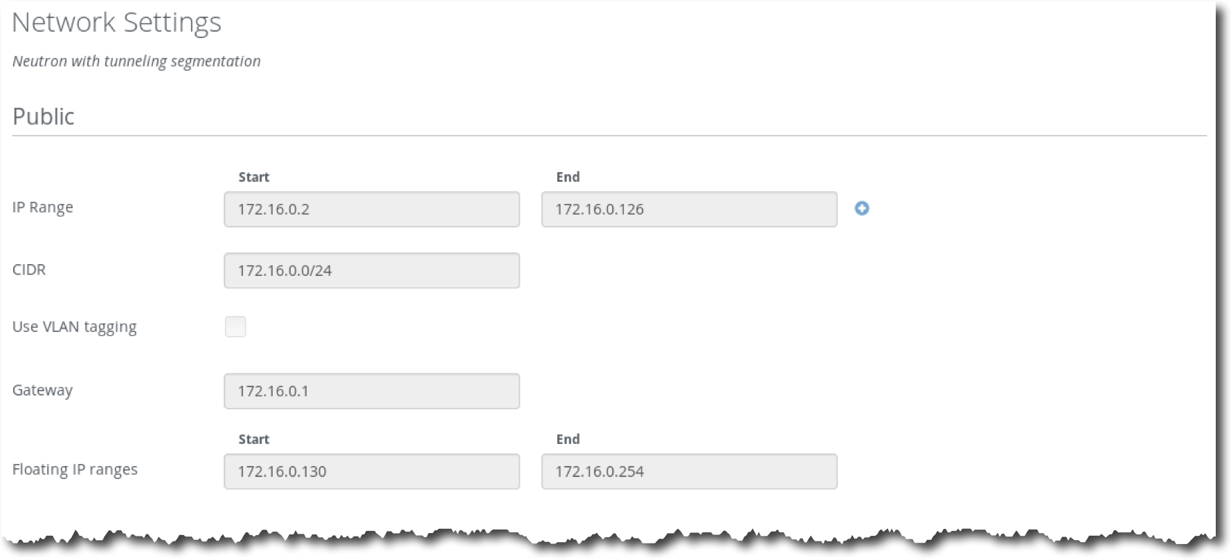
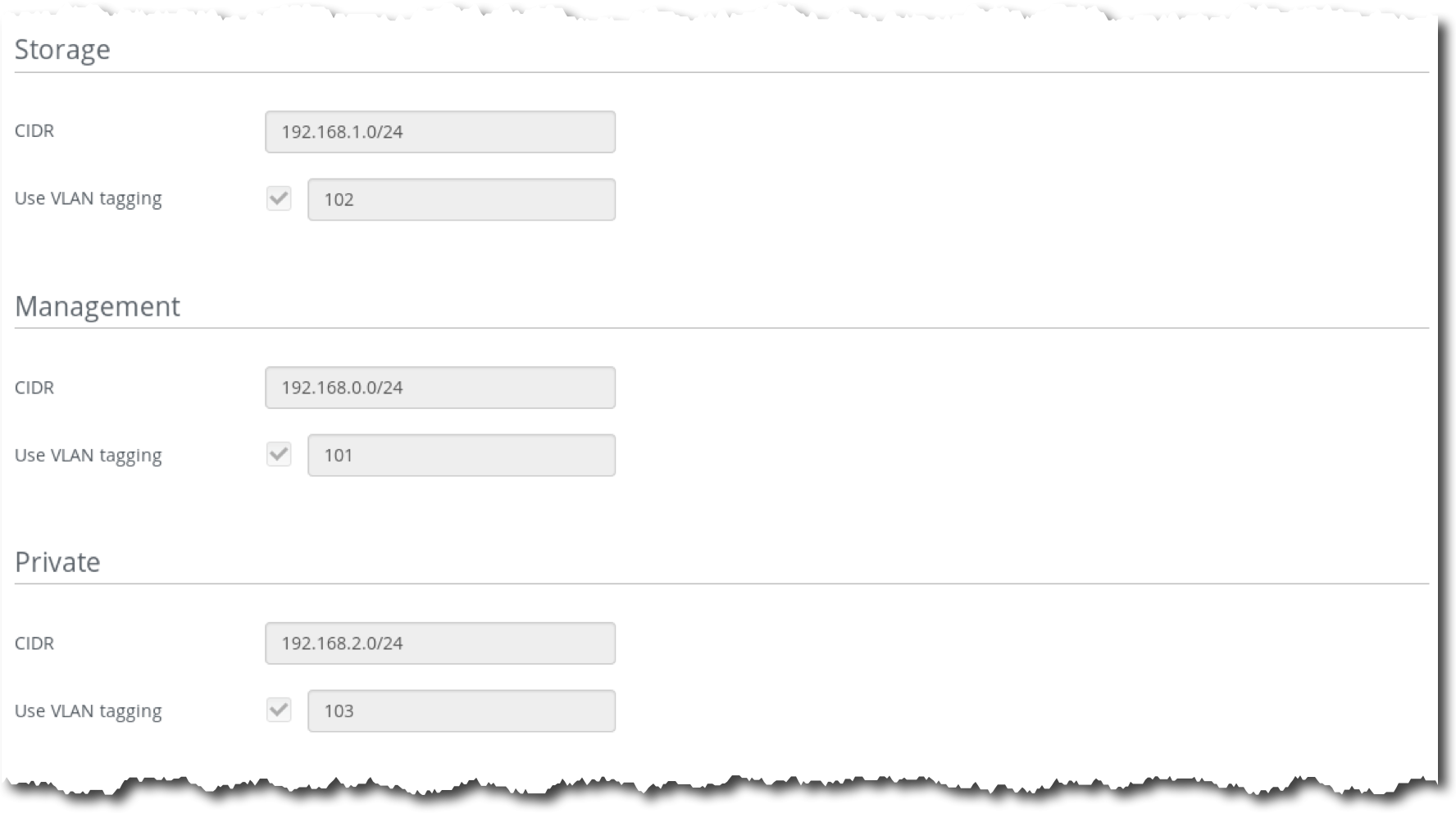
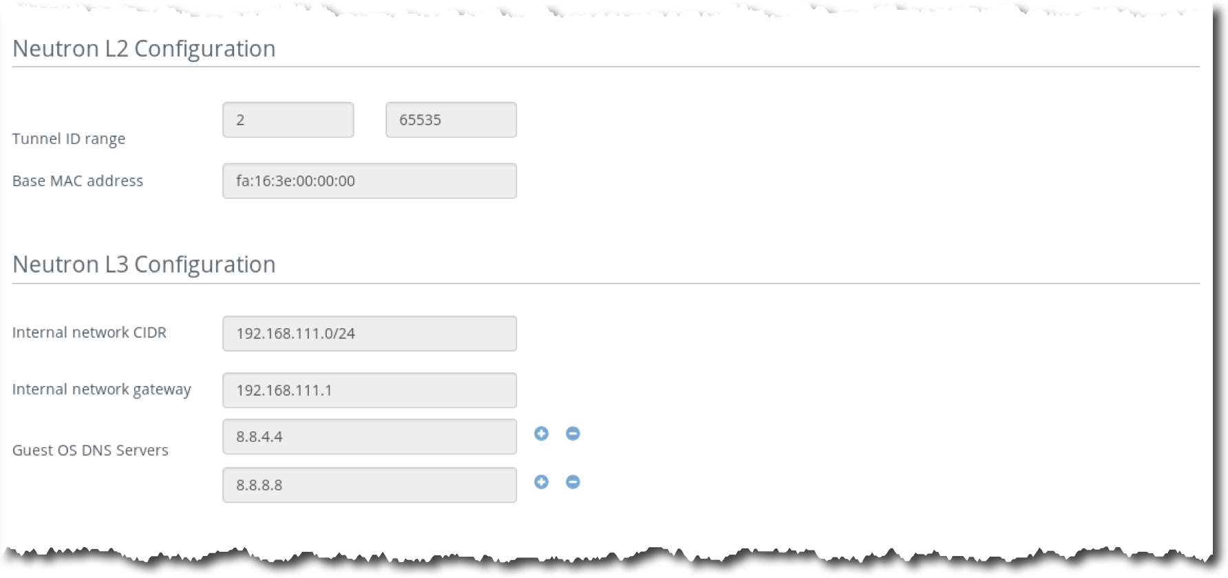
Step 5 Log in to the Fuel UI, choose the environment Test, then choose the tab Networks:
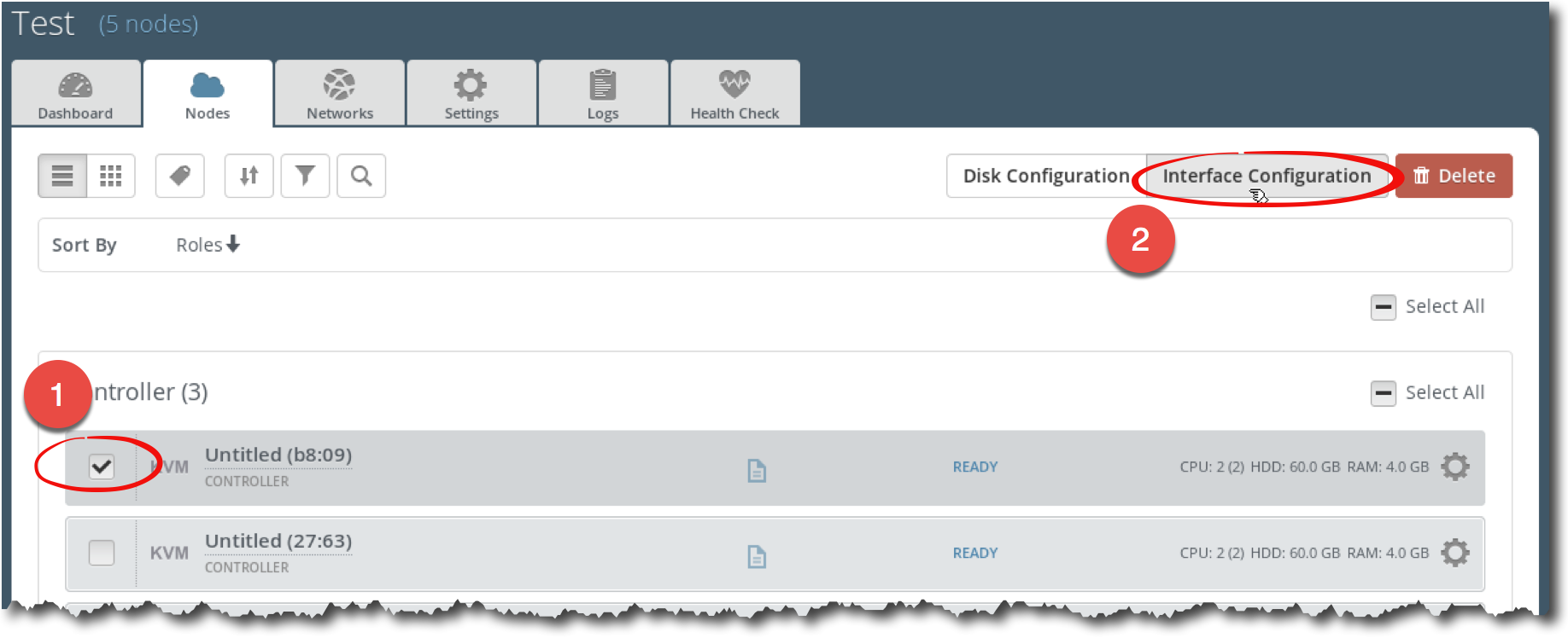
Step 6 In Fuel UI, choose Nodes. Select any controller node and click on Interface Configuration button:
Step 7 In the Interfaces configuration dialog, explore how the networks are assigned to the network interfaces:
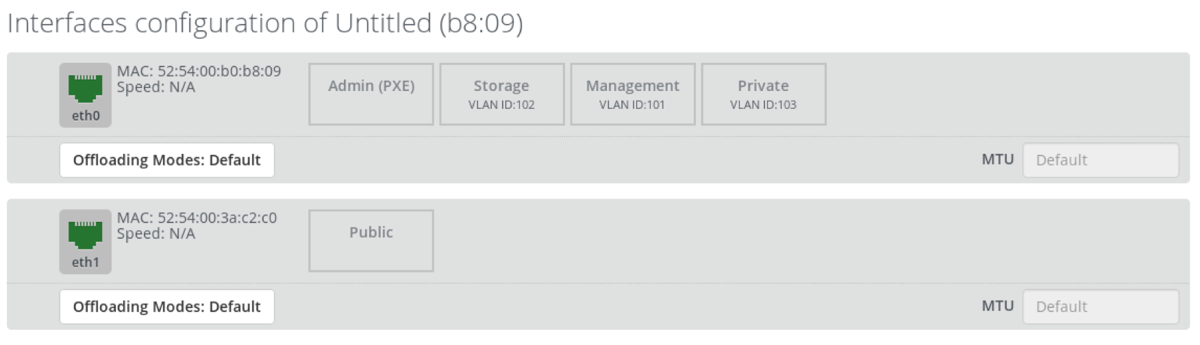
Note that admin and public networks are untagged, storage, management and private networks are assigned to eth0 and tagged by VLAN ID 102, 101 and 103 correspondingly.
Important
For a real world OpenStack deployment, using a single NIC is probably not a good idea:
- The recommended option for the management network is to have a separate NIC for each node to prevents administrative traffic, such as database queries, RabbitMQ messages and cloud admin queries from being disrupted by other traffic.
- Because the private network handles all traffic between VMs it is reasonable to to have a dedicated NIC for each node for the private network.
- Storage traffic (storage network) requires dedicated NICs for storage and compute nodes and ideally there should be a dedicated network and NIC for the replication network (a network for Ceph or Swift replication traffic).
6.4. Launch Test Instances
Let’s explore how Neutron with VXLAN tunneling segmentation works in the existing environment. We will launch three test instances (Test, Test2, Test3), which will be used in the following exercises. We want Test1 and Test3 to be running on compute1 and Test2 running on compute2.
Step 1 Log in to the fuel node:
stack@lab:~$ ssh root@10.20.0.2
root@10.20.0.2's password:
[root@fuel ~]#
Step 2 Use the following command to show the nodes in the existing OpenStack environment:
[root@fuel ~]# fuel nodes
id | status | name             | cluster | ip        | mac               | roles      | pending_roles | online | group_id
---|--------|------------------|---------|-----------|-------------------|------------|---------------|--------|---------
5  | ready  | Untitled (a7:9c) | 1       | 10.20.0.7 | 52:54:00:82:a7:9c | compute    |               | True   | 1
4  | ready  | Untitled (8d:37) | 1       | 10.20.0.3 | 52:54:00:a7:8d:37 | controller |               | True   | 1
3  | ready  | Untitled (e2:c6) | 1       | 10.20.0.6 | 52:54:00:db:e2:c6 | compute    |               | True   | 1
1  | ready  | Untitled (b8:09) | 1       | 10.20.0.5 | 52:54:00:b0:b8:09 | controller |               | True   | 1
2  | ready  | Untitled (27:63) | 1       | 10.20.0.4 | 52:54:00:a7:27:63 | controller |               | True   | 1
Step 3 Use Virtual Machine Manager to map the compute nodes from the output above to “physical” nodes (VMs running in Virtual Machine Manager): double click on compute1, choose Details and get the MAC address for the first network interface:
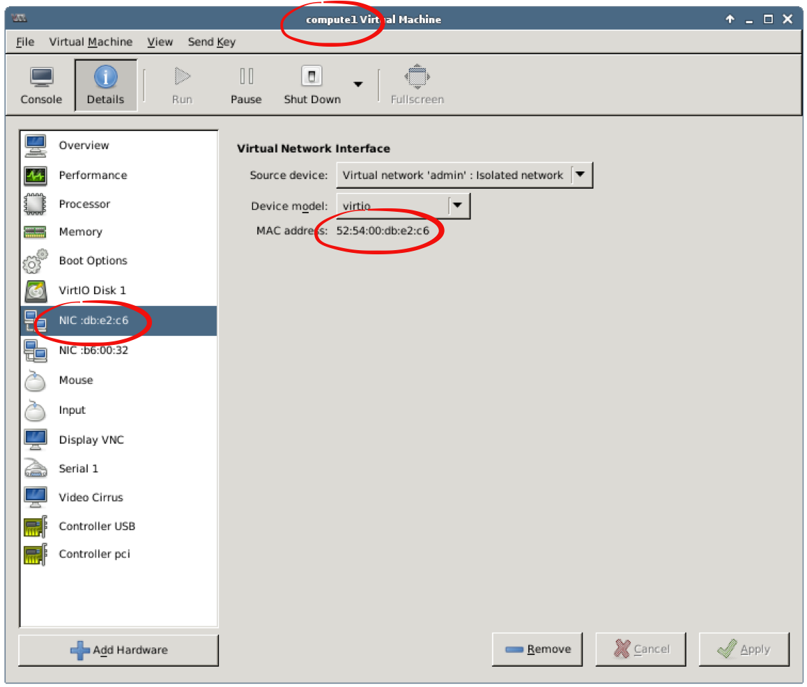
Using the MAC address from the VM’s details, you can map nodes from the output above to the “physical” nodes (VMs in Virtual Machine Manager).
Step 4 Execute the following commands to get host names for the compute nodes:
[root@fuel ~]# host 10.20.0.6
6.0.20.10.in-addr.arpa domain name pointer node-3.domain.tld.
[root@fuel ~]# host 10.20.0.7
7.0.20.10.in-addr.arpa domain name pointer node-5.domain.tld.
[root@fuel ~]#
Alternatively, to get a host name for a node, you can open the compute node’s console to get host name for the selected compute node. Double click on a compute node in Virtual Machine Manager, then Console. Press Enter if the console is blank or does not contain login prompt:
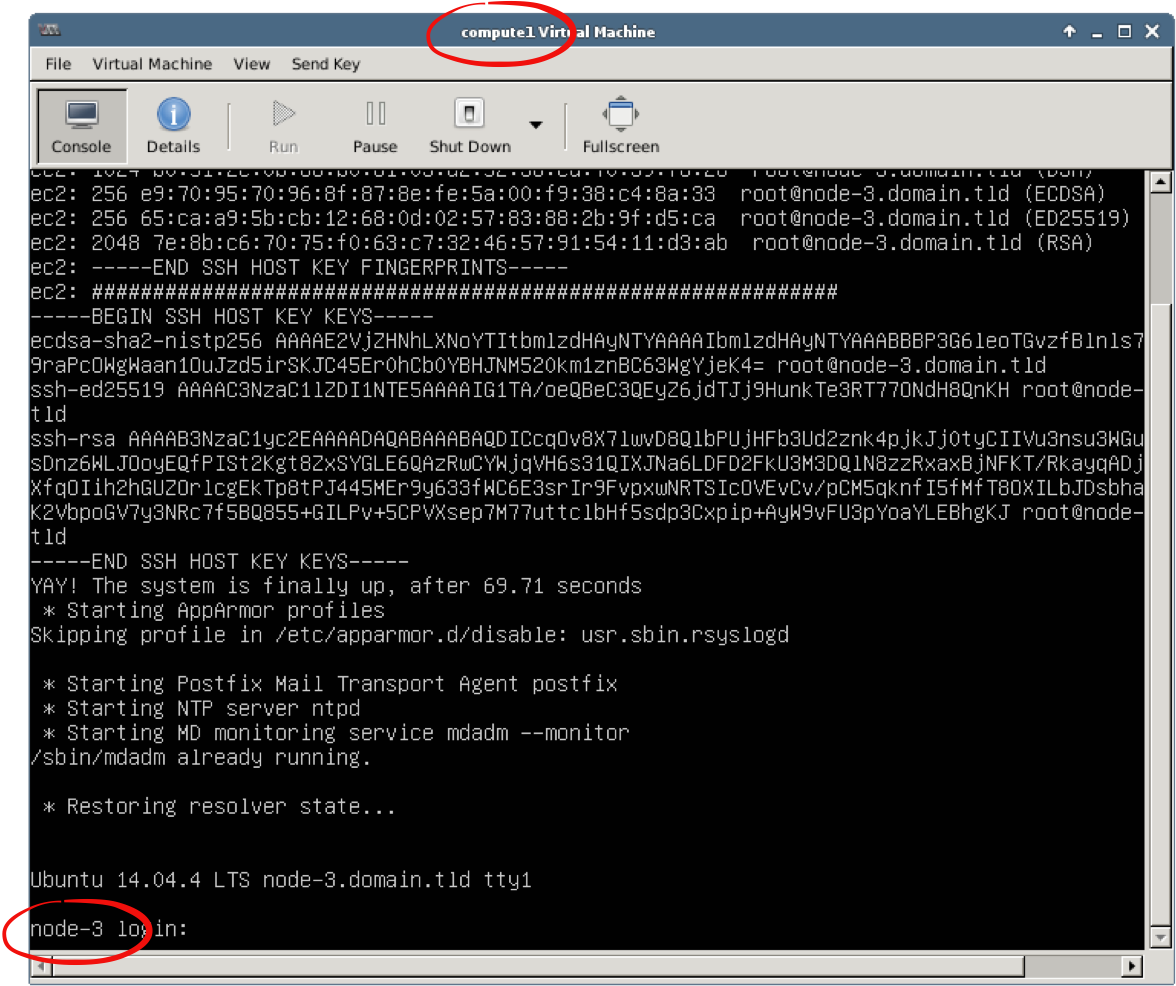
Finally, your mapping should look like this:
- compute1 corresponds to node-3.domain.tld
- compute2 corresponds to node-5.domain.tld
Step 5 Log in to any controller node:
[root@fuel ~]# ssh 10.20.0.3
root@node-4:~#
Step 6 Execute the following commands to show the existing hypervisors:
root@node-4:~# source openrc
root@node-4:~# nova hypervisor-list
+----+---------------------+-------+---------+
| ID | Hypervisor hostname | State | Status  |
+----+---------------------+-------+---------+
| 3  | node-5.domain.tld   | up    | enabled |
| 5  | node-3.domain.tld   | up    | enabled |
+----+---------------------+-------+---------+
Step 7 Execute the following commands to get a list of networks:
root@node-4:~# neutron net-list
+--------------------------------------+-----------+-------------------------------------------------------+
| id                                   | name      | subnets                                               |
+--------------------------------------+-----------+-------------------------------------------------------+
| c4e2f2ba-53a3-472b-9b8e-5f2b5b1e05e2 | net04     | b1372191-3153-44df-a70e-9a41c8e2bfcb 192.168.111.0/24 |
| 7fcb4c69-eb42-415a-8904-ca73817fa526 | net04_ext | 0dafb35f-1411-4b1c-a69d-5d64f809cab7 172.16.0.0/24    |
+--------------------------------------+-----------+-------------------------------------------------------+
Step 8 Launch the Test1 instance on compute1. Use the ID for the network net04 from the output above:
root@node-4:~# nova boot Test1 \
--image TestVM --flavor m1.tiny \
--nic net-id=c4e2f2ba-53a3-472b-9b8e-5f2b5b1e05e2 \
--availability-zone nova:node-3.domain.tld
+--------------------------------------+-----------------------------------------------+
| Property                             | Value                                         |
+--------------------------------------+-----------------------------------------------+
| OS-DCF:diskConfig                    | MANUAL                                        |
| OS-EXT-AZ:availability_zone          | nova                                          |
| OS-EXT-SRV-ATTR:host                 | -                                             |
| OS-EXT-SRV-ATTR:hypervisor_hostname  | -                                             |
| OS-EXT-SRV-ATTR:instance_name        | instance-00000002                             |
| OS-EXT-STS:power_state               | 0                                             |
| OS-EXT-STS:task_state                | scheduling                                    |
| OS-EXT-STS:vm_state                  | building                                      |
| OS-SRV-USG:launched_at               | -                                             |
| OS-SRV-USG:terminated_at             | -                                             |
| accessIPv4                           |                                               |
| accessIPv6                           |                                               |
| adminPass                            | JVTs2oMYxq4j                                  |
| config_drive                         |                                               |
| created                              | 2016-06-22T19:30:15Z                          |
| flavor                               | m1.tiny (1)                                   |
| hostId                               |                                               |
| id                                   | 6163a30b-28c0-4d52-a01e-63ad62fd9169          |
| image                                | TestVM (fa79d4f3-5c75-40ba-8049-04f07e0a7764) |
| key_name                             | -                                             |
| metadata                             | {}                                            |
| name                                 | Test1                                         |
| os-extended-volumes:volumes_attached | []                                            |
| progress                             | 0                                             |
| security_groups                      | default                                       |
| status                               | BUILD                                         |
| tenant_id                            | 77ae2edfa20f4bc48b62d08c1ae2614b              |
| updated                              | 2016-06-22T19:30:14Z                          |
| user_id                              | 6ec127d5fa574b7eb8e7bd533b240b3f              |
+--------------------------------------+-----------------------------------------------+
Step 9 Launch the Test2 instance on compute2. Use the ID for the network net04 from the output above:
root@node-4:~# nova boot Test2 \
--image TestVM --flavor m1.tiny \
--nic net-id=c4e2f2ba-53a3-472b-9b8e-5f2b5b1e05e2 \
--availability-zone nova:node-5.domain.tld
+--------------------------------------+-----------------------------------------------+
| Property                             | Value                                         |
+--------------------------------------+-----------------------------------------------+
| OS-DCF:diskConfig                    | MANUAL                                        |
| OS-EXT-AZ:availability_zone          | nova                                          |
| OS-EXT-SRV-ATTR:host                 | -                                             |
| OS-EXT-SRV-ATTR:hypervisor_hostname  | -                                             |
| OS-EXT-SRV-ATTR:instance_name        | instance-00000005                             |
| OS-EXT-STS:power_state               | 0                                             |
| OS-EXT-STS:task_state                | scheduling                                    |
| OS-EXT-STS:vm_state                  | building                                      |
| OS-SRV-USG:launched_at               | -                                             |
| OS-SRV-USG:terminated_at             | -                                             |
| accessIPv4                           |                                               |
| accessIPv6                           |                                               |
| adminPass                            | eZ2ijfFYC5mY                                  |
| config_drive                         |                                               |
| created                              | 2016-06-22T19:34:30Z                          |
| flavor                               | m1.tiny (1)                                   |
| hostId                               |                                               |
| id                                   | f2e4a002-ceca-4976-88cf-89f61ff24a84          |
| image                                | TestVM (fa79d4f3-5c75-40ba-8049-04f07e0a7764) |
| key_name                             | -                                             |
| metadata                             | {}                                            |
| name                                 | Test2                                         |
| os-extended-volumes:volumes_attached | []                                            |
| progress                             | 0                                             |
| security_groups                      | default                                       |
| status                               | BUILD                                         |
| tenant_id                            | 77ae2edfa20f4bc48b62d08c1ae2614b              |
| updated                              | 2016-06-22T19:34:29Z                          |
| user_id                              | 6ec127d5fa574b7eb8e7bd533b240b3f              |
+--------------------------------------+-----------------------------------------------+
Step 10 Launch the Test3 instance on compute1. Use the ID for the network net04 from the output above:
root@node-4:~# nova boot Test3 \
--image TestVM --flavor m1.tiny \
--nic net-id=c4e2f2ba-53a3-472b-9b8e-5f2b5b1e05e2 \
--availability-zone nova:node-3.domain.tld
+--------------------------------------+-----------------------------------------------+
| Property                             | Value                                         |
+--------------------------------------+-----------------------------------------------+
| OS-DCF:diskConfig                    | MANUAL                                        |
| OS-EXT-AZ:availability_zone          | nova                                          |
| OS-EXT-SRV-ATTR:host                 | -                                             |
| OS-EXT-SRV-ATTR:hypervisor_hostname  | -                                             |
| OS-EXT-SRV-ATTR:instance_name        | instance-00000008                             |
| OS-EXT-STS:power_state               | 0                                             |
| OS-EXT-STS:task_state                | scheduling                                    |
| OS-EXT-STS:vm_state                  | building                                      |
| OS-SRV-USG:launched_at               | -                                             |
| OS-SRV-USG:terminated_at             | -                                             |
| accessIPv4                           |                                               |
| accessIPv6                           |                                               |
| adminPass                            | CZLJ3MMxvAKS                                  |
| config_drive                         |                                               |
| created                              | 2016-06-22T19:35:56Z                          |
| flavor                               | m1.tiny (1)                                   |
| hostId                               |                                               |
| id                                   | 57858f36-1910-4450-9d60-bfe285441b27          |
| image                                | TestVM (fa79d4f3-5c75-40ba-8049-04f07e0a7764) |
| key_name                             | -                                             |
| metadata                             | {}                                            |
| name                                 | Test3                                         |
| os-extended-volumes:volumes_attached | []                                            |
| progress                             | 0                                             |
| security_groups                      | default                                       |
| status                               | BUILD                                         |
| tenant_id                            | 77ae2edfa20f4bc48b62d08c1ae2614b              |
| updated                              | 2016-06-22T19:35:56Z                          |
| user_id                              | 6ec127d5fa574b7eb8e7bd533b240b3f              |
+--------------------------------------+-----------------------------------------------+
Step 10 Verify that you have three instances running:
root@node-4:~# nova list
+--------------------------------------+-------+--------+------------+-------------+---------------------+
| ID                                   | Name  | Status | Task State | Power State | Networks            |
+--------------------------------------+-------+--------+------------+-------------+---------------------+
| 6163a30b-28c0-4d52-a01e-63ad62fd9169 | Test1 | ACTIVE | -          | Running     | net04=192.168.111.5 |
| f2e4a002-ceca-4976-88cf-89f61ff24a84 | Test2 | ACTIVE | -          | Running     | net04=192.168.111.6 |
| 57858f36-1910-4450-9d60-bfe285441b27 | Test3 | ACTIVE | -          | Running     | net04=192.168.111.7 |
+--------------------------------------+-------+--------+------------+-------------+---------------------+
6.5. Explore Compute Node
We will explore how Neutron with VXLAN tunneling segmentation is implemented on the compute node.
Step 1 Open Terminal Emulator, login to the fuel node, then to the compute11 node, which has node-3 host name:
stack@lab:~$ ssh root@10.20.0.2
root@10.20.0.2's password:
[root@fuel ~]# ssh node-3
root@node-3:~#
Step 2 Check that Neutron is configured to use Neutron with VXLAN tunneling segmentation:
root@node-3:~# cat /etc/neutron/plugins/ml2/ml2_conf.ini | grep ^tenant_network_types
tenant_network_types = flat,vlan,vxlan
Step 3 Use the command ovs-vsctl show to show Open vSwitch bridges. Note that there is br-tun bridge:
root@node-3:~# ovs-vsctl show
e8ada576-bf70-4968-b32f-87d419b76a62
    Bridge br-tun
        fail_mode: secure
        Port patch-int
            Interface patch-int
                type: patch
                options: {peer=patch-tun}
        Port "vxlan-c0a80205"
            Interface "vxlan-c0a80205"
                type: vxlan
                options: {df_default="true", in_key=flow, local_ip="192.168.2.1", out_key=flow, remote_ip="192.168.2.5"}
        Port "vxlan-c0a80203"
            Interface "vxlan-c0a80203"
                type: vxlan
                options: {df_default="true", in_key=flow, local_ip="192.168.2.1", out_key=flow, remote_ip="192.168.2.3"}
        Port "vxlan-c0a80202"
            Interface "vxlan-c0a80202"
                type: vxlan
                options: {df_default="true", in_key=flow, local_ip="192.168.2.1", out_key=flow, remote_ip="192.168.2.2"}
        Port "vxlan-c0a80204"
            Interface "vxlan-c0a80204"
                type: vxlan
                options: {df_default="true", in_key=flow, local_ip="192.168.2.1", out_key=flow, remote_ip="192.168.2.4"}
        Port br-tun
            Interface br-tun
                type: internal
...
Step 4 Let’s verify that we can ping other instances from one instance, because they are connected to the same internal network (192.168.111.0/24). Start Firefox, log in to Horizon. From the navigation menu choose Project, Compute, Instances. For Test1 instance, choose Console and log in to Test1 using cirros as the user name and cubswin:) as the password. Check that you can ping Test2 and Test3:
$ ping -c 1 192.168.111.6
...
1 packets transmitted, 1 received, 0% packet loss
...

$ ping -c 1 192.168.111.7
...
1 packets transmitted, 1 received, 0% packet loss
...
Step 5 Let’s modify the default security group to allow SSH traffic for our test instances. From the navigation menu choose Project, Access & Security. For the default security group press Manage Rules button. Press the Add Rule button. Choose SSH in the Rule field, CIDR in the Remote field, 0.0.0.0/0 in the CIDR field. Press the Add button.
Step 6 Return to the compute node node-3. Although we have enabled SSH traffic, the instance Test1 is not directly accessible from the compute node, because the internal network is in a separate namespace and we haven’t associated a floating IP for it:
root@node-3:~# ssh cirros@192.168.111.5
ssh: connect to host 192.168.111.5 port 22: Connection refused
Step 7 To access the Test1 instance via its private IP from the compute node we need to be inside namespace for the internal network. Use the command ip netns list to list namespaces:
root@node-3:~# ip netns list
qrouter-c692a7f5-954c-4397-8536-79a967028799
Use the namespace name from the output above to access the internal network:
root@node-3:~# ip netns exec qrouter-c692a7f5-954c-4397-8536-79a967028799 \
ssh cirros@192.168.111.5
cirros@192.168.111.5's password:
$
6.6. Instances on the same Compute Node
Step 1 Log in to the Test1 instance. You can use the console or ssh to the instance from the compute node, using the technique we discussed above.
Step 2 On the Test1 instance, run ping command for the Test3 instance, which is started on the same compute node. Keep the ping command running:
$ ping 192.168.111.7
PING 192.168.111.7 (192.168.111.7): 56 data bytes
64 bytes from 192.168.111.7: seq=0 ttl=64 time=4.935 ms
64 bytes from 192.168.111.7: seq=1 ttl=64 time=1.848 ms
64 bytes from 192.168.111.7: seq=2 ttl=64 time=5.677 ms
...
Step 3 In a new Terminal Emulator window, log in to the compute1 node (node-3) and execute the following command:
root@node-3:~# watch -n 1 ovs-ofctl dump-ports br-tun
Every 1.0s: ovs-ofctl dump-ports br-tun
OFPST_PORT reply (xid=0x2): 6 ports
  port  4: rx pkts=148, bytes=23944, drop=0, errs=0, frame=0, over=0, crc=0
           tx pkts=164, bytes=22092, drop=0, errs=0, coll=0
  port LOCAL: rx pkts=0, bytes=0, drop=0, errs=0, frame=0, over=0, crc=0
           tx pkts=0, bytes=0, drop=0, errs=0, coll=0
  port  1: rx pkts=670, bytes=114651, drop=0, errs=0, frame=0, over=0, crc=0
           tx pkts=687, bytes=114058, drop=0, errs=0, coll=0
  port  5: rx pkts=78, bytes=12894, drop=0, errs=0, frame=0, over=0, crc=0
           tx pkts=164, bytes=21140, drop=0, errs=0, coll=0
  port  2: rx pkts=338, bytes=55182, drop=0, errs=0, frame=0, over=0, crc=0
           tx pkts=521, bytes=89876, drop=0, errs=0, coll=0
  port  3: rx pkts=123, bytes=22038, drop=0, errs=0, frame=0, over=0, crc=0
           tx pkts=255, bytes=42531, drop=0, errs=0, coll=0
Note that the packet counters (pkts) do not change, so traffic to an instance on the same compute node does not go through tunnel.
6.7. Instances on different Compute Nodes
Step 1 Return to the Test1 instance, terminate ping command and run ping command for the Test2 instance, which is started on different compute node compute2. Keep the ping command running:
$ ping 192.168.111.6
PING 192.168.111.6 (192.168.111.6): 56 data bytes
64 bytes from 192.168.111.6: seq=0 ttl=64 time=4.935 ms
64 bytes from 192.168.111.6: seq=1 ttl=64 time=1.848 ms
64 bytes from 192.168.111.6: seq=2 ttl=64 time=5.677 ms
...
Step 2 Return to the Terminal Emulator window where the command ovs-ofctl dump-ports br-tun is running. Now you can see that the packet counters (pkts) increase every second, so traffic to an instance on different compute node goes through tunnel.
Step 3 In a new Terminal Emulator window, log in to the compute2 node (node-5) and install the tshark package:
root@node-5:~# apt-get install tshark
Step 4 With the ping still running, execute the following command to capture 1 frame on the eth0 interface, filtered by the destination port 4789 (default VXLAN destination port) and save it to the file:
root@node-5:~# tshark -i eth0 -V -c 1 dst port 4789 > vxlan.txt
Step 5 Open the vxlan.txt file:
Frame 1: 152 bytes on wire (1216 bits), 152 bytes captured (1216 bits) on interface 0
    Interface id: 0
    Encapsulation type: Ethernet (1)
    ...
    Frame Number: 1
    Frame Length: 152 bytes (1216 bits)
    Capture Length: 152 bytes (1216 bits)
    [Frame is marked: False]
    [Frame is ignored: False]
    [Protocols in frame: eth:vlan:ip:udp:data]
Note that the Encapsulation type is Ethernet and the Protocols in frame are eth:vlan:ip:udp:data.
Next, find the destination and source sections:
Ethernet II, Src: RealtekU_db:e2:c6 (52:54:00:db:e2:c6), Dst: RealtekU_82:a7:9c (52:54:00:82:a7:9c)
    Destination: RealtekU_82:a7:9c (52:54:00:82:a7:9c)
        Address: RealtekU_82:a7:9c (52:54:00:82:a7:9c)
        ...
    Source: RealtekU_db:e2:c6 (52:54:00:db:e2:c6)
        Address: RealtekU_db:e2:c6 (52:54:00:db:e2:c6)
        ...
    Type: 802.1Q Virtual LAN (0x8100)
Note that the source MAC address is the compute1 MAC address, where the Test1 instance is running. The destination MAC address is the compute2 MAC address, where the Test2 instance is running.
Step 6 Log in to any controller node and terminate the Test2 and Test3 instances:
root@node-4:~# source openrc
root@node-4:~# nova delete Test{2,3}
6.8. OpenStack routing with Distributed Virtual Routing (DVR)
Let’s explore routing in OpenStack with the DVR extension for Neutron. The goal of DVR is to distribute networking datapath of tenants across several nodes running the neutron-l3-agent daemon process. The overall routing responsibilities are separated as described below:
- The network node which is running the neutron-l3-agent process is responsible for providing default north-south SNAT traffic coming from instances that do not have an associated floating IP address.
- The compute nodes are running the neutron-l3-agent process which will be responsible for providing north-south DNAT traffic coming to and from instances that have an associated floating IP address.
- The compute nodes are running the neutron-l3-agent process which will be responsible for providing east-west traffic going to and from instances that are connected through a Neutron router.
Note
6.8.1. Create network topology
To explore the inner workings of how DVR works, let’s create a new network and subnet, and attach them to the pre-existing router. We will then create an instance that is attached to the newly created network.
Step 1 In Terminal Emulator, log in to the Fuel master node and then log in to any controller node:
stack@lab:~$ ssh root@10.20.0.2
root@10.20.0.2's password:

[root@fuel ~]# fuel nodes
id | status | name             | cluster | ip        | mac               | roles      | pending_roles | online | group_id
---|--------|------------------|---------|-----------|-------------------|------------|---------------|--------|---------
5  | ready  | Untitled (a7:9c) | 1       | 10.20.0.7 | 52:54:00:82:a7:9c | compute    |               | True   | 1
4  | ready  | Untitled (8d:37) | 1       | 10.20.0.3 | 52:54:00:a7:8d:37 | controller |               | True   | 1
3  | ready  | Untitled (e2:c6) | 1       | 10.20.0.6 | 52:54:00:db:e2:c6 | compute    |               | True   | 1
1  | ready  | Untitled (b8:09) | 1       | 10.20.0.5 | 52:54:00:b0:b8:09 | controller |               | True   | 1
2  | ready  | Untitled (27:63) | 1       | 10.20.0.4 | 52:54:00:a7:27:63 | controller |               | True   | 1

[root@fuel ~]# ssh 10.20.0.3

root@node-4:~#
Step 2 Create a new network and subnet:
root@node-4:~# source openrc
root@node-4:~# neutron net-create net05
Created a new network:
+---------------------------+--------------------------------------+
| Field                     | Value                                |
+---------------------------+--------------------------------------+
| admin_state_up            | True                                 |
| id                        | ee878fba-28ef-4737-8da4-41e01f360279 |
| mtu                       | 1450                                 |
| name                      | net05                                |
| provider:network_type     | vxlan                                |
| provider:physical_network |                                      |
| provider:segmentation_id  | 47                                   |
| router:external           | False                                |
| shared                    | False                                |
| status                    | ACTIVE                               |
| subnets                   |                                      |
| tenant_id                 | 77ae2edfa20f4bc48b62d08c1ae2614b     |
+---------------------------+--------------------------------------+

root@node-4:~# neutron subnet-create --name net05__subnet \
--dns-nameserver 8.8.4.4 --dns-nameserver 8.8.8.8 \
net05 192.168.122.0/24
Created a new subnet:
+-------------------+------------------------------------------------------+
| Field             | Value                                                |
+-------------------+------------------------------------------------------+
| allocation_pools  | {"start": "192.168.122.2", "end": "192.168.122.254"} |
| cidr              | 192.168.122.0/24                                     |
| dns_nameservers   | 8.8.4.4                                              |
|                   | 8.8.8.8                                              |
| enable_dhcp       | True                                                 |
| gateway_ip        | 192.168.122.1                                        |
| host_routes       |                                                      |
| id                | 76bd8bb9-04ef-42d0-bf4a-29689a3a132c                 |
| ip_version        | 4                                                    |
| ipv6_address_mode |                                                      |
| ipv6_ra_mode      |                                                      |
| name              | net05__subnet                                        |
| network_id        | cee878fba-28ef-4737-8da4-41e01f360279                |
| subnetpool_id     |                                                      |
| tenant_id         | 77ae2edfa20f4bc48b62d08c1ae2614b                     |
+-------------------+------------------------------------------------------+
Step 3 Retrieve list of existing routers:
root@node-4:~# neutron router-list -c id -c name
+--------------------------------------+----------+
| id                                   | name     |
+--------------------------------------+----------+
| c692a7f5-954c-4397-8536-79a967028799 | router04 |
+--------------------------------------+----------+
Connect router listed from previous command to the previously created subnet:
root@node-4:~# neutron router-interface-add router04 net05__subnet
Added interface fd31ad27-1b45-448e-9591-d88078090ec6 to router router04.
Step 4 Launch the Test_net05 instance on compute2. Use the ID for the network net05 from the output above:
root@node-4:~# nova boot Test_net05 \
--image TestVM --flavor m1.tiny \
--nic net-id=ee878fba-28ef-4737-8da4-41e01f360279 \
--availability-zone nova:node-5.domain.tld
+--------------------------------------+-----------------------------------------------+
| Property                             | Value                                         |
+--------------------------------------+-----------------------------------------------+
| OS-DCF:diskConfig                    | MANUAL                                        |
| OS-EXT-AZ:availability_zone          | nova                                          |
| OS-EXT-SRV-ATTR:host                 | -                                             |
| OS-EXT-SRV-ATTR:hypervisor_hostname  | -                                             |
| OS-EXT-SRV-ATTR:instance_name        | instance-00000011                             |
| OS-EXT-STS:power_state               | 0                                             |
| OS-EXT-STS:task_state                | scheduling                                    |
| OS-EXT-STS:vm_state                  | building                                      |
| OS-SRV-USG:launched_at               | -                                             |
| OS-SRV-USG:terminated_at             | -                                             |
| accessIPv4                           |                                               |
| accessIPv6                           |                                               |
| adminPass                            | DUJ98idoYyrd                                  |
| config_drive                         |                                               |
| created                              | 2016-07-06T16:57:03Z                          |
| flavor                               | m1.tiny (1)                                   |
| hostId                               |                                               |
| id                                   | 5c721e88-ea62-4000-ac2b-00dffc2f53c6          |
| image                                | TestVM (fa79d4f3-5c75-40ba-8049-04f07e0a7764) |
| key_name                             | -                                             |
| metadata                             | {}                                            |
| name                                 | Test_net05                                    |
| os-extended-volumes:volumes_attached | []                                            |
| progress                             | 0                                             |
| security_groups                      | default                                       |
| status                               | BUILD                                         |
| tenant_id                            | 77ae2edfa20f4bc48b62d08c1ae2614b              |
| updated                              | 2016-07-06T16:57:02Z                          |
| user_id                              | 6ec127d5fa574b7eb8e7bd533b240b3f              |
+--------------------------------------+-----------------------------------------------+
Step 5 Start Firefox and open the following link: https://172.16.0.3. Use name admin and password admin to log in. Firefox may complain about using the untrusted connection, see 1.5. Working with Firefox for a workaround.
Step 6 From the navigation menu choose Project, Network, Network Topology.
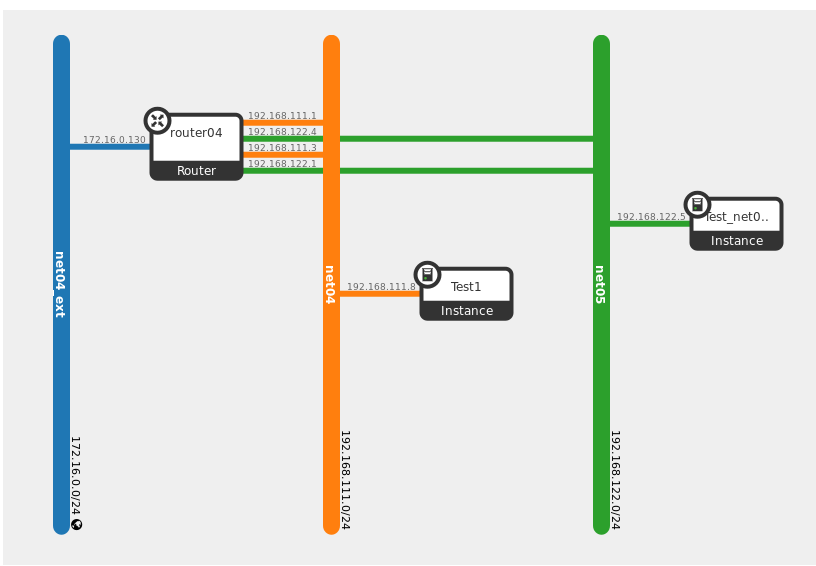
In the topology diagram, you will find two connections between router04 and both the net04 and net05 networks. One of those connections will serve as the gateway for default north-south source NAT (SNAT) traffic, whereas the other connection serves as the default gateway for both north-south Destination NAT (DNAT) floating IP traffic as well as east-west communication going between instances that are attached to different networks that are connected through a Neutron router. We will spend some time looking as to how that is implemented under the hood shortly.
6.8.2. Explore north-south SNAT traffic flow
The first scenario we will explore is how traffic flows from an instance with only a fixed (private) IP out to the Internet. This flow begins on the compute node where the instance is executing and will hit the controller node that is currently responsible for providing the SNAT functionality for Neutron.
Step 1 Start two Terminal Emulator processes. SSH in to Fuel master node as user root with password r00tme in both Terminal Emulator windows:
# In window 1
stack@lab:~$ ssh root@10.20.0.2
[root@fuel ~]#

# In window 2
stack@lab:~$ ssh root@10.20.0.2
[root@fuel ~]#
Step 2 We will use our Test1 instance that we created earlier in this flow. In Terminal Emulator window 1 from the previous step, log in to the compute node hosting the VM:
# In window 1
[root@fuel ~]# ssh node-3
root@node-3:~#
Step 3 Determine the controller node currently responsible for managing SNAT routing. In Terminal Emulator window 2, log in to any controller node and run the following command:
# In window 2
[root@fuel ~]# ssh node-4
root@node-4:~# crm resource show vip__vrouter_pub
resource vip__vrouter_pub is running on: node-1.domain.tld
root@node-4:~# exit
Step 4 In Terminal Emulator window 2, log in to the controller node determined in the previous step from the Fuel master node and set environment variables:
# In window 2
[root@fuel ~]# ssh node-1
root@node-1:~# source openrc
Step 5 There will be several network namespaces that have been created on the controller node. As a general standard, when OpenStack creates resources it uses the resource ID when naming the underlying implementation of that resource. In this case, we can align the network namespace for router04 by mapping it’s ID to the network namespace that contains that same ID:
# In window 2
root@node-1:~# neutron router-list -c id -c name
+--------------------------------------+----------+
| id                                   | name     |
+--------------------------------------+----------+
| c692a7f5-954c-4397-8536-79a967028799 | router04 |
+--------------------------------------+----------+
Using the id above, list network namespaces that contain that value:
root@node-1:~# ip netns list | grep c692a7f5-954c-4397-8536-79a967028799
snat-c692a7f5-954c-4397-8536-79a967028799
qrouter-c692a7f5-954c-4397-8536-79a967028799
From the output above, we can see that there are two network namespaces that exist with that ID in their respective names.
- snat-*: Provides the appropriate routing table entries and IPtables rules to handle external communication.
- qrouter-*: Provides default routing between networks connected to our router router04.
Step 6 In Terminal Emulator window 1, list the network namespaces just as we did in the previous step:
# In window 1
root@node-3:~# ip netns list | grep c692a7f5-954c-4397-8536-79a967028799
qrouter-c692a7f5-954c-4397-8536-79a967028799
From the output above, we can see that there is only one network namespaces that exists with that ID.
- qrouter-*: Will provide east-west routing between networks connected to our router router04 and will also be used in floating IP traffic flow.
Step 7 Let’s begin connecting the chain of networking resources that will carry traffic from the instance all the way out to the Internet. First, retrieve the name of the instance on the hypervisor on which it is running. In Terminal Emulator window 2, get details of Test1:
# In window 2
root@node-1:~# nova show Test1 | grep instance_name
| OS-EXT-SRV-ATTR:instance_name | instance-0000000b |
We already know which compute node the Test1 instance is running on and we have already SSHed into that system back over in Terminal Emulator window 1. In that window, list out the running virtual machines and you will see one with the same name as we see in the output in the previous command:
# In window 1
root@node-3:~# virsh list
 Id    Name                           State
----------------------------------------------------
 3     instance-0000000b              running
Using the Id from the output, list out network interfaces assigned to the instance:
root@node-3:~# virsh domiflist 3
Interface      Type       Source         Model       MAC
----------------------------------------------------------------------
tap658f8759-d4 bridge     qbr658f8759-d4 virtio      fa:16:3e:f4:c4:35
The output above shows two main things:
- tap*: The name of the Linux tap device that was created and assigned to the instance at provisioning time.
- qbr*: The name of the Linux bridge that is used as a workaround for IPtables rules to function properly with OpenvSwitch.
Now we can see how the qbr* device connects to the OpenvSwitch bridge:
root@node-3:~# brctl show qbr658f8759-d4
bridge name     bridge id               STP enabled     interfaces
qbr658f8759-d4  8000.82786d456526       no              qvb658f8759-d4
                                                        tap658f8759-d4
The output above shows a device named qvb*. This is one end of a veth pair, a virtual patch cable that consists of two devices which connects the Linux bridge, and, in turn the instance to the OpenvSwitch bridge br-int. To see the other end of the veth pair, execute the following command:
root@node-3:~# ethtool -S qvb658f8759-d4
NIC statistics:
     peer_ifindex: 24
Use the value of peer_ifindex from the output above and execute the following command:
root@node-3:~# ip link show | grep 24:
24: qvo658f8759-d4: <BROADCAST,MULTICAST,PROMISC,UP,LOWER_UP> mtu 65000 ...
The qvo device listed above is connected to the OpenvSwitch bridge br-int. This can be seen by executing the following command:
root@node-3:~# ovs-vsctl show
...
Bridge br-int
  fail_mode: secure
  Port "qvo658f8759-d4"
    tag: 1
    Interface "qvo658f8759-d4"
...
From the output above, we can also determine that our Test1 instance is isolated on local VLAN 1 due to the tag: 1 line.
Let’s recap what we have found out so far. Our instance is running on one of our compute nodes. The instance was assigned a tap device, which is then plugged into a Linux bridge (qbr) device, which is then connected to our OpenvSwitch bridge (br-int) through a veth pair, where one end of the pair (qvb) is connected to the Linux bridge (qbr), and the other end of the veth pair (qvo) is attached to the OpenvSwitch bridge (br-int). The qvo device is isolated on VLAN 1 on the OpenvSwitch bridge, meaning it can communicate directly with other devices on that VLAN across br-int as they are located on the same layer 2 broadcast domain.
To summarize: when a packet leaves our Test1 instance, it goes through the devices as such:
tap -> qbr -> qvb -> qvo -> VLAN 1 on br-int
Let’s use the scenario here where Test1 is looking to communicate with a device on the Internet. Test1 will forward the packet to it’s default gateway which is 192.168.111.1. This can be verified by logging in to the instance.
Step 8 Start Firefox and open the following link: https://172.16.0.3. Use name admin and password admin to log in. Firefox may complain about using the untrusted connection, see 1.5. Working with Firefox for a workaround.
From the navigation menu choose Project, Instances. From Actions next to the Test1 instance choose Console to open VM console. Press Click here to show only console. You can log in to the VM using user name cirros and password cubswin:).
Step 9 From within the instance Console, execute the following commands to see how it’s networking has been configured:
$ ip addr show eth0
2: eth0: <BROADCAST,MULTICAST,UP,LOWER_UP> mtu 1450 qdisc pfifo_fast qlen 1000
    link/ether fa:16:3e:f4:c4:35 brd ff:ff:ff:ff:ff:ff
    inet 192.168.111.8/24 brd 192.168.111.255 scope global eth0
    inet6 fe80::f816:3eff:fef4:c435/64 scope link
       valid_lft forever preferred_lft forever

$ ip route
default via 192.168.111.1 dev eth0
169.254.169.254 via 192.168.111.1 dev eth0
192.168.111.0/24 dev eth0  src 192.168.111.8

$ arp -a
? (192.168.111.1) at fa:16:3e:b8:c6:a5 [ether]  on eth0
Note the default gateway IP address and MAC address in the ARP cache. The device this correlates to is found on the compute node where the instance is running and will be found on the same local VLAN as the instance on the br-int OpenvSwitch device.
Step 10 In Terminal Emulator window 1, execute the following command:
# In window 1
root@node-3:~# ovs-vsctl show
...
Bridge br-int
  fail_mode: secure
  Port "qvo658f8759-d4"
    tag: 1
    Interface "qvo658f8759-d4"
  Port "qr-23402e65-07"
    tag: 1
    Interface "qr-23402e65-07"
...
From the output above, we can see there is only one other device on the same local VLAN as the instance - qr-23402e65-07 in this case. Let’s look at how this device has been configured.
Step 11 Execute the following commands in Terminal Emulator window 1. Ensure you replace the device name with what you found in the previous step:
# In window 1
root@node-3:~# ip addr show qr-23402e65-07
Device "qr-23402e65-07" does not exist.
The device cannot be found because it exists within a qrouter-* namespace.
Step 12 Re-execute the previous command within the router namespace:
root@node-3:~# ip netns list
qrouter-c692a7f5-954c-4397-8536-79a967028799

root@node-3:~# ip netns exec qrouter-c692a7f5-954c-4397-8536-79a967028799 \
ip addr show qr-23402e65-07
27: qr-23402e65-07: <BROADCAST,MULTICAST,UP,LOWER_UP> ...
    link/ether fa:16:3e:b8:c6:a5 brd ff:ff:ff:ff:ff:ff
    inet 192.168.111.1/24 brd 192.168.111.255 scope global qr-23402e65-07
      valid_lft forever preferred_lft forever
    inet6 fe80::f816:3eff:feb8:c6a5/64 scope link
      valid_lft forever preferred_lft forever
The device should hold the same IP address and MAC address as what was seen within Test1‘s network configuration.
With DVR, as stated earlier, default north-south SNAT traffic flows out through the network node (controller node in Fuel deployed environments). Let’s examine how packets will flow from the compute node over to the controller node.
Step 13 Gain shell access into the router namespace and look at routing entries that will be used to forward packets to the controller node:
# In window 1
root@node-3:~# ip netns exec qrouter-c692a7f5-954c-4397-8536-79a967028799 \
bash
root@node-3:~#
Step 14 Examine routing entries in router namespace:
root@node-3:~# ip route
192.168.111.0/24 dev qr-23402e65-07  proto kernel  scope link  src 192.168.111.1
192.168.122.0/24 dev qr-fd31ad27-1b  proto kernel  scope link  src 192.168.122.1
The above output shows just two routes for this router. One for net04__subnet and the other for net05__subnet. On Linux, it is possible to have different routing policies that can map different rules to different routing tables. This is what is used in this particular scenario to forward packets to the controller node.
Step 15 List out routing policy rules:
root@node-3:~# ip rule list
0:      from all lookup local
32766:  from all lookup main
32767:  from all lookup default
3232263937:     from 192.168.111.1/24 lookup 3232263937
3232266753:     from 192.168.122.1/24 lookup 3232266753
Since Test1 sends it’s packets to it’s default gateway of 192.168.111.1, the 2nd to last line indicates the routing table to use to make a routing decision (3232263937)
Step 16 Using the routing table ID from the previous command, evaluate the entries in the routing table:
root@node-3:~# ip route show table 3232263937
default via 192.168.111.3 dev qr-23402e65-07
The route above indicates to forward packets out through the qr device to 192.168.111.3. This is an IP address assigned to an interface that exists on the controller node hosting the snat* namespace that we SSHed into previously in Terminal Emulator window 2.
Step 17 In Terminal Emulator window 2, examine network namespaces that have been created and start a shell session within the snat-<qrouter id> namespace:
# In window 2
root@node-1:~# ip netns list
snat-c692a7f5-954c-4397-8536-79a967028799
...

root@node-1:~# ip netns exec snat-c692a7f5-954c-4397-8536-79a967028799 bash
root@node-1:~#
Step 18 List out network interfaces in snat* namespace from previous step:
root@node-1:~# ip addr
...
58: sg-707d7804-89: <BROADCAST,MULTICAST,UP,LOWER_UP> ...
    link/ether fa:16:3e:4c:8e:7c brd ff:ff:ff:ff:ff:ff
    inet 192.168.111.3/24 brd 192.168.111.255 scope global sg-707d7804-89
      valid_lft forever preferred_lft forever
    inet6 fe80::f816:3eff:fe4c:8e7c/64 scope link
      valid_lft forever preferred_lft forever
...
The packet flows from the compute node, out onto the VXLAN segment, and will arrive at the sg device seen in the output from the above command.
Step 19 Examine the routing table entries and IPtables rules that are responsible for routing packets to the public network and performing SNAT:
root@node-1:~# ip route
default via 172.16.0.1 dev qg-feb44eba-83
172.16.0.0/24 dev qg-feb44eba-83  proto kernel  scope link  src 172.16.0.130
192.168.111.0/24 dev sg-707d7804-89  proto kernel  scope link  src 192.168.111.3
192.168.122.0/24 dev sg-52612b30-5a  proto kernel  scope link  src 192.168.122.4

root@node-1:~# iptables -t nat -nvL
...
Chain neutron-l3-agent-snat (1 references)
pkts bytes target prot opt in out             source      destination
  15  1133 SNAT    all  --  * qg-feb44eba-83  0.0.0.0/0   0.0.0.0/0   to:172.16.0.130
...

Chain neutron-postrouting-bottom (1 references)
pkts bytes target                prot opt in out source    destination
  15  1133 neutron-l3-agent-snat  all --   *   * 0.0.0.0/0   0.0.0.0/0 /* Perform source NAT on outgoing traffic. */
The routes indicate the packet will flow out through a qg* device that has an IP address of 172.16.0.130. The IPtables rules indicate that the source IP field of packets going out through the same qg* device should be changed to 172.16.0.130.
Step 20 If you don’t already have Firefox launched, do so and navigate to Horizon at 172.16.0.3. Log in with user admin and password admin, then navigate to Project, Network, Network Topology. You should find the interface connecting router04 to net04_ext has the same IP address as what you saw in the two previous steps.
Step 21 Tidy up your current work environment by exiting out of each SSH session and closing each Terminal Emulator window you have opened.
6.8.3. Explore north-south DNAT traffic flow
The second scenario we will explore is how traffic flows from an instance with a floating IP out to the Internet. This flow happens entirely on the compute node where the instance is executing.
Step 1 Launch Terminal Emulator and log in to Fuel master node as user root with password r00tme:
stack@lab:~# ssh root@10.20.0.2
[root@fuel ~]#
Step 2 Log in to any controller node:
[root@fuel ~]# fuel nodes
id | status | name             | cluster | ip        | mac               | roles      | pending_roles | online | group_id
---|--------|------------------|---------|-----------|-------------------|------------|---------------|--------|---------
5  | ready  | Untitled (a7:9c) | 1       | 10.20.0.7 | 52:54:00:82:a7:9c | compute    |               | True   | 1
4  | ready  | Untitled (8d:37) | 1       | 10.20.0.3 | 52:54:00:a7:8d:37 | controller |               | True   | 1
3  | ready  | Untitled (e2:c6) | 1       | 10.20.0.6 | 52:54:00:db:e2:c6 | compute    |               | True   | 1
1  | ready  | Untitled (b8:09) | 1       | 10.20.0.5 | 52:54:00:b0:b8:09 | controller |               | True   | 1
2  | ready  | Untitled (27:63) | 1       | 10.20.0.4 | 52:54:00:a7:27:63 | controller |               | True   | 1

[root@fuel ~]# ssh 10.20.0.3
root@node-4:~#
Step 3 Retrieve list of compute instances and note IP address for Test_net05 instance:
root@node-4:~# source openrc
root@node-4:~# nova list
+----------+------------+--------+------------+-------------+---------------------+
| ID       | Name       | Status | Task State | Power State | Networks            |
+----------+------------+--------+------------+-------------+---------------------+
| d47ddf0f | Test1      | ACTIVE | -          | Running     | net04=192.168.111.8 |
| 5c721e88 | Test_net05 | ACTIVE | -          | Running     | net05=192.168.122.5 |
+----------+------------+--------+------------+-------------+---------------------+
Step 4 Retrieve Neutron port id for IP associated with Test_net05 instance:
root@node-4:~# neutron port-list -c id -c fixed_ips | grep 192.168.122.5
| 528e4d2f | {"subnet_id": "76bd8bb9", "ip_address": "192.168.122.5"} |
Step 5 Create a floating IP and associate it with the port found in the previous step:
root@node-4:~# neutron floatingip-create --port-id 528e4d2f net04_ext
Step 6 Determine the compute node and VM name on the hypervisor for the Test_net05 instance:
root@node-4:~# nova show Test_net05
...
| OS-EXT-SRV-ATTR:hypervisor_hostname  | node-5.domain.tld |
| OS-EXT-SRV-ATTR:instance_name        | instance-00000011 |
...

root@node-4:~# exit
Step 7 Log in to the compute node found in the previous step:
[root@fuel ~]# ssh node-5
root@node-5:~#
Step 8 List network interfaces assigned to VM found above:
root@node-5:~# virsh domiflist instance-00000011
Interface      Type       Source         Model       MAC
----------------------------------------------------------------------
tap528e4d2f-fc bridge     qbr528e4d2f-fc virtio      fa:16:3e:44:0b:ec
Step 9 View devices connected to qbr* device found in previous step:
root@node-5:~# brctl show qbr528e4d2f-fc
bridge name     bridge id               STP enabled     interfaces
qbr528e4d2f-fc  8000.e29917dc60ec       no              qvb528e4d2f-fc
                                                        tap528e4d2f-fc
Step 10 Determine veth peer for qvb*:
root@node-5:~# ethtool -S qvb528e4d2f-fc
NIC statistics:
     peer_ifindex: 30

root@node-5:~# ip link show | grep 30:
30: qvo528e4d2f-fc: <BROADCAST,MULTICAST,PROMISC,UP,LOWER_UP> ...
Step 11 Examine OpenvSwitch device br-int to determine local VLAN for this VM and other devices found on the same VLAN segment:
root@node-5:~# ovs-vsctl show
...
Bridge br-int
  fail_mode: secure
  Port "qr-fd31ad27-1b"
    tag: 2
    Interface "qr-fd31ad27-1b"
    type: internal
  Port patch-tun
    Interface patch-tun
    type: patch
    options: {peer=patch-int}
  Port "qvo528e4d2f-fc"
    tag: 2
    Interface "qvo528e4d2f-fc"
  Port "qr-23402e65-07"
    tag: 1
    Interface "qr-23402e65-07"
    type: internal
From the output above, we can see that qr-fd31ad27-1b and qvo528e4d2f-fc are both located on the same VLAN segment. The qr-fd31ad27-1b device is the router gateway for the network that our instance is connected to.
Step 12 Retrieve list of network namespaces present on the compute node:
root@node-5:~# ip netns list
fip-7fcb4c69-eb42-415a-8904-ca73817fa526
qrouter-c692a7f5-954c-4397-8536-79a967028799
We should see two network namespaces now. There is our regular qrouter* one just like what was seen in the previous flow. The other namespace, fip*, is one part to how the floating IP is implemented for our instance. Let’s explore that.
Step 13 Start a shell session within the qrouter* namespace found in the previous step:
root@node-5:~# ip netns exec qrouter-c692a7f5-954c-4397-8536-79a967028799 \
bash
root@node-5:~#
Step 14 List out network interface configuration for the router:
root@node-5:~# ip addr
...
2: rfp-c692a7f5-9: <BROADCAST,MULTICAST,UP,LOWER_UP> ...
    link/ether 0a:55:31:6e:dd:04 brd ff:ff:ff:ff:ff:ff
    inet 169.254.31.28/31 scope global rfp-c692a7f5-9
      valid_lft forever preferred_lft forever
    inet 172.16.0.132/32 brd 172.16.0.132 scope global rfp-c692a7f5-9
      valid_lft forever preferred_lft forever
    inet6 fe80::855:31ff:fe6e:dd04/64 scope link
      valid_lft forever preferred_lft forever
23: qr-23402e65-07: <BROADCAST,MULTICAST,UP,LOWER_UP> ...
    link/ether fa:16:3e:b8:c6:a5 brd ff:ff:ff:ff:ff:ff
    inet 192.168.111.1/24 brd 192.168.111.255 scope global qr-23402e65-07
      valid_lft forever preferred_lft forever
    inet6 fe80::f816:3eff:feb8:c6a5/64 scope link
      valid_lft forever preferred_lft forever
24: qr-fd31ad27-1b: <BROADCAST,MULTICAST,UP,LOWER_UP>
    link/ether fa:16:3e:62:26:06 brd ff:ff:ff:ff:ff:ff
    inet 192.168.122.1/24 brd 192.168.122.255 scope global qr-fd31ad27-1b
      valid_lft forever preferred_lft forever
    inet6 fe80::f816:3eff:fe62:2606/64 scope link
      valid_lft forever preferred_lft forever
We see three devices in the output above. There are two qr* devices, each serving the purpose of being the default gateway for a tenant network. The rfp* device is where we see the floating IP that we associated with our instance earlier on in this exercise. We also see a second IP address on that device - 169.254.31.28 in the output above.
Step 15 Examine the rules in IPtables that will perform DNAT and SNAT from floating IP to fixed IP and vice-versa:
root@node-5:~# iptables -t nat -nvL
...
Chain neutron-l3-agent-PREROUTING (1 references)
 pkts bytes target prot opt in out source    destination
    0     0 DNAT   all  --  *  *   0.0.0.0/0 172.16.0.132 to:192.168.122.5

...

Chain neutron-l3-agent-float-snat (1 references)
 pkts bytes target prot opt in out source        destination
    0     0 SNAT   all  --  *  *   192.168.122.5 0.0.0.0/0   to:172.16.0.132
Step 16 Examine the routing table rules and corresponding entries:
root@node-5:~# ip rule list
root@node-5:~# ip rule list
0:      from all lookup local
32766:  from all lookup main
32767:  from all lookup default
32768:  from 192.168.122.5 lookup 16
3232263937:     from 192.168.111.1/24 lookup 3232263937
3232266753:     from 192.168.122.1/24 lookup 3232266753
There is a rule indicating that when traffic is coming from 192.168.122.5 (fixed IP of instance), lookup table 16 and use the routing table entries found there:
root@node-5:~# ip route show table 16
default via 169.254.31.29 dev rfp-c692a7f5-9
The route states to forward packets out through the rfp* device we previously saw in the qrouter* namepsace to 169.254.31.29.
Step 17 Gather information regarding the rfp* device and how traffic is routed:
root@node-5:~# ethtool -i rfp-c692a7f5-9
driver: veth
version: 1.0
firmware-version:
bus-info:
supports-statistics: yes
supports-test: no
supports-eeprom-access: no
supports-register-dump: no
supports-priv-flags: no
From the output above, it becomes apparent the rfp* device is a veth pair.
Step 18 Determine veth peer for rfp* device:
root@node-5:~# ethtool -S rfp-c692a7f5-9
NIC statistics:
     peer_ifindex: 2
Here we see that the veth peer has the index of 2.
Exit from the qrouter namespace:
root@node-5:~# exit
Step 19 Start a shell session within the fip* namespace:
root@node-5:~# ip netns list
fip-7fcb4c69-eb42-415a-8904-ca73817fa526
qrouter-c692a7f5-954c-4397-8536-79a967028799

root@node-5:~# ip netns exec fip-7fcb4c69-eb42-415a-8904-ca73817fa526 \
bash
root@node-5:~#
Notes
The ID that follows fip in the namespace name corresponds with the ID of the Neutron network where the floating IP came from. If you have multiple instances on a single compute node with floating IPs, they will all have veth pairs going from their respective qrouter namespace over to the fip namespace.
Step 20 List out interfaces in fip* namespace and identify the interface that is the veth peer that was found earlier:
root@node-5:~# ip addr | grep -A5 '^2:'
2: fpr-c692a7f5-9: <BROADCAST,MULTICAST,UP,LOWER_UP> ...
    link/ether 86:c7:be:c1:42:d4 brd ff:ff:ff:ff:ff:ff
    inet 169.254.31.29/31 scope global fpr-c692a7f5-9
      valid_lft forever preferred_lft forever
    inet6 fe80::84c7:beff:fec1:42d4/64 scope link
      valid_lft forever preferred_lft forever
The IP address we see on the device at index 2 corresponds with the IP address that we saw as the default route for traffic coming from the fixed IP of the instance.
Step 21 Finally, list out the routing table entries in the fip* namespace to examine where packets will go when they depart, and how they will be routed on the way back:
root@node-5:~# ip route
default via 172.16.0.1 dev fg-f78fcf69-d8
169.254.31.28/31 dev fpr-c692a7f5-9  proto kernel  scope link  src 169.254.31.29
172.16.0.0/24 dev fg-f78fcf69-d8  proto kernel  scope link  src 172.16.0.133
172.16.0.132 via 169.254.31.28 dev fpr-c692a7f5-9
Congratulations! You have successfully explored the OpenStack environment configured to use Neutron with VXLAN tunneling segmentation and Distributed Virtual Routing (DVR).
Checkpoint
- Explore underlying networks
- Explore OpenStack networks
- Launch instances on different compute nodes
- Explore the traffic flow between two instances on the same compute node and on different compute nodes
![]()
Table Of Contents
- 1. Classroom Environment
- 2. Explore HA OpenStack
- 3. Fuel Installation
- 4. Simple Deployment
- 5. HA Deployment
- 6. OpenStack Networking
- 7. Fuel Troubleshooting
- 8. Fuel Plugins
- 9. OpenStack with Ceph
- 10. Murano
- 11. Sahara